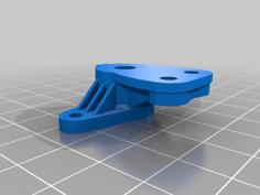
V2 MF-01X Mid Motor Conversion 3D Printer Model
The file 'V2 MF-01X Mid Motor Conversion 3D Printer Model' is (stl) file type, size is 752.3KB.
The file 'V2 MF-01X Mid Motor Conversion 3D Printer Model' is (stl) file type, size is 752.3KB.
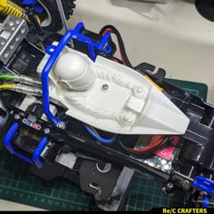
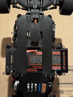
This is updated version of my MF-01X conversion. Designed from scratch, it addresses feedback from users as well as my own findings and ideas. This version is much more modular, I will post number of modifications as remixes and encourage anyone to post their own :)
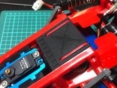
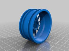
As with the previous version, S, M and L wheelbases are supported with the stock chassis inserts and modified stock propshafts, with longer wheelbase variants possible through their combinations or custom inserts.
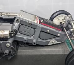
The conversion replaces A2, A4, B10 and B11 chassis parts (+number of other kit parts mounted to them). Disassemble this part of the kit, as gears, axles, screws and other parts are reused in this conversion.
If you didn't build the previous version, you'll need these extra parts:
The M-chassis gear set (#54277 or #50794) is used again to create identical gear ratio to other Tamiya M-chassis. Other required parts are:
If you built the previous version, you'll only need two extra 1150 bearings used for the propshaft - these replace the 1050 bearings used before.
Screws:
To assemble the gearbox, you can reuse kit BA6 3x10mm self tapping screws, the kit contains all screws needed with one exception - one of the screws may be used for servo horn. In that case, you can use the BA3 3x10mm machine screw.
Eventually, you can use M3x10 machine screws on the rest of the gearbox. You'll need 24pcs total, including screws for the body mounts and connection to the rest of the chassis.
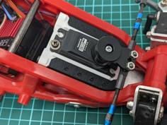
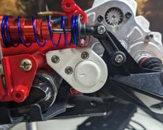
The motor is mounted using the stock 3x27mm screws and metal plate. Correct pinion position is same as the kit one - you can use stock “pinion stopper” part, both MF-01X and M-chassis gear set variants work.
List of improvements:
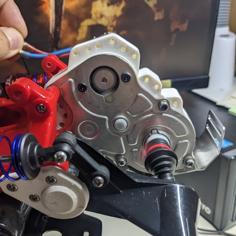
There were other minor changes for easier printing and assembly. Different gear layout resulted in shorter propeller shaft compared to the previous version - just drilling a new hole for the cross pin, using the included jig, is enough to address this.
Printing
I recommend printing from PETG, the model is designed for 0.2mm layer height and three perimeters.
Activate “solid infill threshold” and set 15mm^2 value - this is to fill up small areas around the suspension mount screws.
The motor mount should be printed from ASA or similar high tempeature material, to make it more resistant against motor heat.
Supports are necessary on some parts, but you can activate “don't support bridges” to reduce amount of support material.
For optimal results, try higher temps and lower fan speeds with slow perimeter speed - this should provide maximum Z strength for PETG parts.
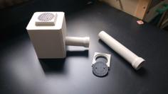
Important information regarding fan use:
Motor magnets interfere with the fan's hall sensors. Depending on motor type, fan type and relative position of the two, fan may need to be rotated in the pocket to work, but some combinaions may perform poorly or not work at all. Test your configuration before closing the gearbox. I tested mine on a Sunon 5V fan and cheap no-name fan, with positive results.
| bevelcover.stl | 142.7KB | |
| damperstay.stl | 109.1KB | |
| fanblank.stl | 20.2KB | |
| gearcover.stl | 216.8KB | |
| gearholder.stl | 92.0KB | |
| lefthalf.stl | 656.5KB | |
| motormount.stl | 177.5KB | |
| pinioncover.stl | 15.9KB | |
| righthalf.stl | 593.1KB | |
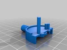
| shaftjig.stl | 39.2KB | |
| suspensionmount.stl | 145.9KB |