Ultrasonic Experiments 2: Standing Wave 3D Printer Model
The file 'Ultrasonic Experiments 2: Standing Wave 3D Printer Model' is (pdf,stl) file type, size is 180.1KB.
The file 'Ultrasonic Experiments 2: Standing Wave 3D Printer Model' is (pdf,stl) file type, size is 180.1KB.
I have developed a series of experiments with ultrasound waves that can be done by students in upper-level physics lessons. The experiments will be presented in arbitrary order in the future.
These experiments include:
1: reflection and absorption of ultrasonic waves
2: standing waves
3: interference with two transmitters
4: the double-slit experiment
5: the effect of a semipermeable plate
6: the Michelson interferometer
7: the Mach-Zehnder interferometer
8: the distance measurement with an Arduino
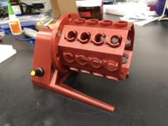
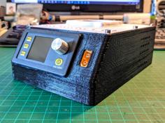
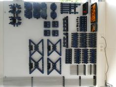
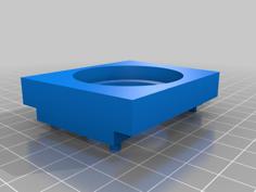
curcuit_board_mount: For the curcuit i used a board of 5cm x 7cm, which is sufficent for the ultrasonic sound generator. I chose a standard curcuit with the NE555. The mount can be printed without a support.
mount for horn: this print ist the mount for the transmitter and the reciever horn. For this experiment yue will need two of them. No support
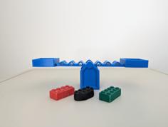
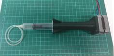
horn: For this horn i choose an angle of approx. 20 degrees. For this experiment you will need two of them. No support.
simple horn: An alternative horn.
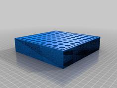
base: For this part i used the excellent work of jandetlefsen and his thing http://www.thingiverse.com/thing:1412135. I could not find anything more suitable nor could I develop something better myself.
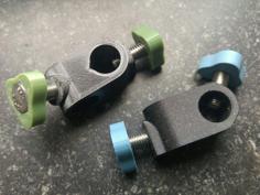
nut M3 and nut_M3_2x: a generic nut for M3 for the 20x20 aluminium profile system: For this experiment you will need three of them.
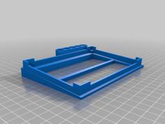
mount for plate : support is necessary.
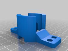
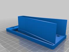
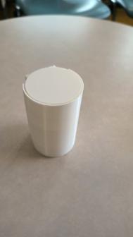
mount for a small reciever : When examining a standing wave, one must detect the area of the wave in a way to disturb the standing wave itself as little as possible. Therefore, this component has been built very narrow. The detector is obtained by opening a standard ultrasonic reciever (UST-40R) very, very carefully.
Aluminium profiles: for this experiment i recommend one 50cm long profiles
Screws and nuts: a lot of M3 screws for mounting on the profiles (M3 x 10mm, M3 x 16mm), some M5 screws for the bases.
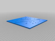
Aluminium plate: i recommend a plate of 150mm x 150mm with a thickness of 2mm as a reflector
Moving the detector slowly on the rail, then you can see about every 4mm that the signal has a maximum (corresponding to the half of the wavelength).
| ultrasonic_experiments_transmitter_and_reciever.pdf | 35.3KB | |
| ultrasonic_exp_base.stl | 96.4KB | |
| ultrasonic_exp_curcuit_board_mount.stl | 169.9KB | |
| ultrasonic_exp_horn.stl | 69.1KB | |
| ultrasonic_exp_horn_simple.stl | 25.5KB | |
| ultrasonic_exp_mount_for_horn.stl | 42.9KB | |
| ultrasonic_exp_mount_for_plate.stl | 43.1KB | |
| ultrasonic_exp_mount_for_small_reciever.stl | 68.1KB | |
| ultrasonic_exp_nut_M3.stl | 25.7KB | |
| ultrasonic_exp_nut_M3_2x.stl | 60.8KB |