Ultraportable Yagi-Uda Antenna For VHF/UHF 3D Printer Model
The file 'Ultraportable Yagi-Uda Antenna For VHF/UHF 3D Printer Model' is (stl) file type, size is 151.6KB.
The file 'Ultraportable Yagi-Uda Antenna For VHF/UHF 3D Printer Model' is (stl) file type, size is 151.6KB.
The idea behind this project is to provide a basket of parts out of which anyone can assemble his or her customized Yagi-Uda antenna for VHF/UHF. For my initial 2m - antenna an additional goal was to come up with an ultraportable design. Both was achieved and if you want to create your own one, this is what you will need in addition to the 3D-printed parts:
Bill of materials:
Aluminum square tube, outer dimension 20 mm of appropriate length
Aluminum tube, outer diam. 6 mm, wall thickness 1mm of the appropriate length for radiator, reflector(s) and director(s)
(Min.) 100 mm threaded rod, M5
(Min.) 8 nuts, M5
2 nuts: 1/4'' USC
1 BNC-connector
2 solder lugs for 5 mm
2 plastic caps for the aluminum square tube
As you will have to cut M5 inner threads into the aluminum tubes you will also need the respective tools for that.
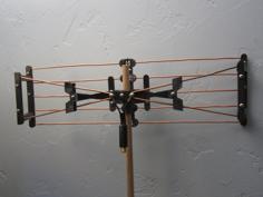
The design for my 3-element 2m band antenna is described in detail in the magazine "Funkamateur 09/2015". These are the dimensions (tip to tip), as listed in the magazine: reflector 1034 mm, radiator 988 mm, director 884 mm. The distance between the radiator rods at the feedpoint is 10 mm, distance between reflector and radiator 350 mm and between reflector and director 600 mm. Most convenient - and the reason for "cuttting in halve" of director and reflector - is the fact that all the element parts fit inside the squared aluminum tube which acts at the same time as the mounting bracket for the antenna. Thus the antenna is just 62 cm long and a few centimeters wide for transport and well protected.
Deviating from the above mentioned article, I found the SWR better, when shortening the director by 40 mm. So my version of the 2m band antenna has a director length of 844 mm. All other dimensions are the same as above.
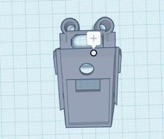
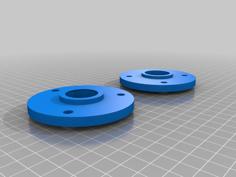
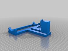
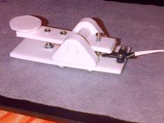
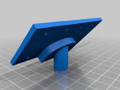
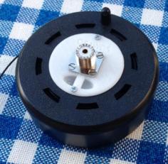
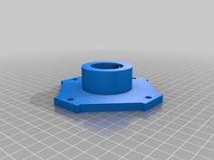
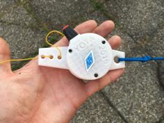
The attachment part for a tripod is designed in such a way, that the antenna can be mounted horizontally as well as vertically. The USC-nuts have to be glued in their places, preferrably using a 2 component epoxy resin. As the antenna should stay clear of conducting parts (e.g. tripod) it is advisable to increase the distance to the tripod by means of an extension (like:http://www.thingiverse.com/thing:1641926). It is also a good idea to reduce common mode, for example by attaching a foldable ferrite or some turns of the antenna cable.
| Attachment_part_for_tripod.stl | 27.2KB | |
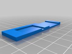
| Cover_for_radiator_mounting.stl | 58.4KB | |
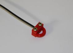
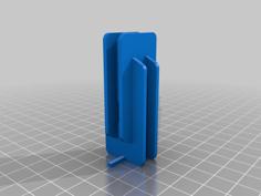
| Holder_for_5mm_antenna_cable.stl | 13.0KB | |
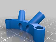
| Mounting_for_director_and_reflector.stl | 45.6KB | |
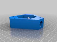
| Mounting_for_radiator.stl | 207.4KB | |
| yagi-uda_antenna_for_vhfuhf.stl | 347.7KB |