This Is A Hobby Radio Project For A Variable Air Capacitor With A Gear System 3D Printer Model
The file 'This Is A Hobby Radio Project For A Variable Air Capacitor With A Gear System 3D Printer Model' is (FCStd,stl,pdf) file type, size is 10.2MB.
The file 'This Is A Hobby Radio Project For A Variable Air Capacitor With A Gear System 3D Printer Model' is (FCStd,stl,pdf) file type, size is 10.2MB.
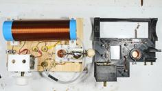
This is a Hobby Radio project for a Variable Air Capacitor with a gear system. The concept is based around the idea of simply making “breadboard” components / systems to explore various radio circuit ideas. It not meant to be used for a permanent radio design. My plan is to explore the enormous crystal and then early vacuum tube radio circuit designs just for the fun and exploration of it. So check out my projects and videos as I grind though a lot of ideas!
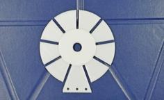
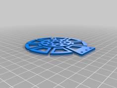
The design is 3D printed so is very easy to make. The gear system is a 2 to 1 ratio. However being air capacitors such as this one have only a 180 degree turn, this design in effect produces a 4 to 1 ratio. This allows for very little effort to find very fine tuning of the capacitor so such things as needing such a fine motion to hit just the right spot is made much easier. This design as the added benefit of eliminating a major trouble of body capacitance. The face plate has space for mounting a graduated placard. Also on the faceplate is a little window that shows the gear appearing as the second turn is starting. This gives a clue to look at the second set of graduations on the dial. A graph is also provided to give some idea as the the capacitance at various angles that may prove helpful.
The Capacitor system is based around a new air cap that can be bought at Amazon. See the link:
I have seen this same model sold at many of the little independent hobby radio parts suppliers on the internet. Assuming those are the same model they seem to sell for less. However I can’t confirm their the same.
Check out my YouTube Video to see all the details of the design, its printing, assembly and use.
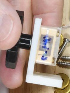
The air cap has 6-32 mount holes on the base that I’ve used to mount the caps to my gear system. The electrical connections for stator will need to be bent 90 degrees and one lead sniped off for mounting to the 3D printed frame. The rotor connection is via the frame and the mounting base screws. Naturally check to see the screws are not too long as to hit the stator vanes. The air cap has some insulator plates that extend a bit past the base of the frame and would be stressed if the base was simply mounted without some spacers. For that I’ve used some 10-32 washers and ground one side to make a D shape. This allows for the washers to be centered over the 6-32 screw holes and keep the washers clear of the protruding insulators.
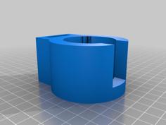
The large gear is mounted via a compression hub. On the gear is 3 holes for 4-40 brass melt in screw nut inserts. The compression hub will press fingers on the gear to the ¼” rotor shaft. The gear is positioned so when the air cap vanes are fully meshed the gear is also facing over the vanes, evenly centered. Carefully hold the gear to keep the alignment while evenly tightening the screws to compress the hub to the face of the gear.
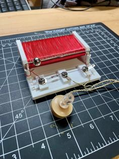
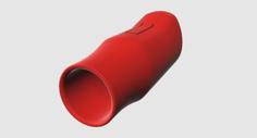
The control knob has an integral gear that meshes to the larger gear. The knob is simply held in place with a snap in clip. When mounting the cap to the frame align the knob pointer to the top and have the cap vanes fully meshed or full open. After all is tightened down it maybe necessary to force the knob a bit at the capacitor limits to force the shaft to slip a bit to get the last bit of alignment. Naturally be careful of such a method not to cause damage. The other thought is to simply rotate the paper with the graduated marking a bit to make all aligned.
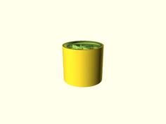
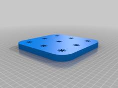
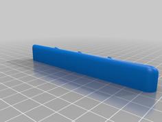
The base plate has pockets for inserting 6-32 nuts. A couple of screws then mount the face plate to the base. The base plate has some holes and room to mount some components, such as coils and such.
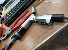
For my project plans the devices have crimped Molex pins such as was used for the old hard drive power plugs.
https://en.wikipedia.org/wiki/Molex_connector
The devices such as capacitors or coils use female ends and the interconnecting wires are the male crimped connectors. For my application I don’t bother with any of the plastic housings used to make connectors, I just use the bare pin / plugs. This makes for very inexpensive and quick way of connecting devices for circuit playing around.
So that’s really all there is to it. Check out my YouTube Thingiverse sites for progress on new ideas.
https://www.youtube.com/channel/UCtBGrxdGsbbyz9oZk8mKJbA/videos
https://www.thingiverse.com/the_id_of_ed/designs
Enjoy,
| Air_Cap_Gear_Compression_Hub_mnt_ver.FCStd | 3.4MB | |
| Air_Cap_Gear_Compression_Hub_mnt_ver.stl | 1.2MB | |
| Base_Panel_mount_3D_print_angle_face.FCStd | 141.4KB | |
| Base_Panel_mount_3D_print_angle_face.stl | 1.0MB | |
| Clip_Knob_Shaft.FCStd | 93.1KB | |
| Clip_Knob_Shaft.stl | 21.8KB | |
| Compress_Hub.FCStd | 18.7KB | |
| Compress_Hub.stl | 31.7KB | |
| Dial_0-50_X_100_.pdf | 60.4KB | |
| Gear_Knob_side.FCStd | 3.9MB | |
| Gear_Knob_side_deep_knurling.stl | 708.8KB | |
| Gear_Knob_side_light_knurling.stl | 737.3KB | |
| New_Air_Cap_Gear_Drive_Mnt_Panel.FCStd | 508.6KB | |
| New_Air_Cap_Gear_Drive_Mnt_Panel.stl | 371.9KB | |
| New_Air_Cap_Gear_Drv_Panel_Mnt_Assembly.FCStd | 901.1KB | |
| New_Manufacture_Var_Air_Cap_Mockup.FCStd | 58.5KB |