Space:1999 Commlock – Prop With Basic LED Lighting 3D Printer Model
The file 'Space:1999 Commlock – Prop With Basic LED Lighting 3D Printer Model' is (stl,pdf) file type, size is 1.0MB.
The file 'Space:1999 Commlock – Prop With Basic LED Lighting 3D Printer Model' is (stl,pdf) file type, size is 1.0MB.
UPDATE: It was brought to my attention that I had uploaded the wrong body files - they were too large. This Thing has now been updated with V2 body files that are the correct size for the rest of the parts. My apologies to anyone who grabbed the earlier files.
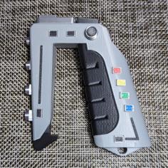
This is a very slightly interactive prop of the Commlock communications and door pass device from the 1970s Gerry Anderson show, Space:1999. I recently got caught up in a Space:1999 stun gun project, so making a Commlock was the next obvious choice!
It's designed to be printed in multiple filament colours and then glued together, rather than being painted. I used the following colours:
The various buttons, and other surface detail, should be glued into the appropriate depressions on the body - refer to the attached photos for the correct locations.
It is also designed to have the screen light up using a simple LED setup. This is why the larger linker part is so long - that should only be glued to the top of the body, and then the top and mid body slide fit, so the unit can be taken apart to get at batteries and such held inside.
The electronics are extremely simple:
The circuit is assembled as follows:
If you don't fancy breaking out the soldering iron, just glue the silver switch cap into the hole in the top of the body, and you are all good.
The translucent screen should be glued to the back of the screen hood, there are no alignment marks, but it should be centred over the aperture. When that has set, the hood can be glued to the top of the body - the screen will help centre the hood.
I've also included PDFs for the various decals. I printed them out on an inkjet, laminated them, and then cut them to size. I applied them with double-sided tape.
And yes, the font on the keypad is not correct, but I don't know what the actual font used on the prop was - so if anyone does know, do please let me know!
| CommLock-BlackButtons.stl | 143.8KB | |
| CommLock-BodyBase-V2.stl | 217.6KB | |
| CommLock-BodyMid-V2.stl | 252.5KB | |
| CommLock-BodyTop-V2.stl | 342.5KB | |
| CommLock-GreyLinkers.stl | 188.0KB | |
| CommLock-KeyPad.pdf | 24.0KB | |
| CommLock-LEDMount.stl | 158.2KB | |
| CommLock-MomentarySwitchMount.stl | 253.7KB | |
| CommLock-PhotoID.pdf | 199.3KB | |
| CommLock-RWGButtons.stl | 6.5KB | |
| CommLock-ScreenAndHood.stl | 65.7KB | |
| CommLock-SilverParts.stl | 927.5KB | |
| CommLock-TuningPad.pdf | 48.0KB |