Es hat nun etwas gedauert, aber hier ist es: das nächste Level! Wer noch nicht weiß worum es geht, der schaut in der Linkliste weiter unten nach dem ersten Teil (Level 0) von SAMBUCCA, dort wird erklärt was SAMBUCCA ist. Dort habe ich auch versprochen in diesem Teil zu erklären warum ich dieses Projekt mache. Nun, eigentlich kann man mit dem fertigen SAMBUCCA nicht so viel machen. Man kann etwas damit spielen, das war es aber auch schon. Aber der Weg ist bekanntlich das Ziel, und so lernt man bei der Entstehung dieses Vehikels viel über Microcontroller, Programmieren, Schaltungsentwurf, Zusammenspiel von Teilen, Mechanik, Mathematik, Umgang mit Werkzeugen und Software. Theoretisch also ein Lern-Projekt für den Schreibtisch. Darum also, weil ich herausfinden will ob ich es kann.
Aufgabe dieses Levels von SAMBUCCA
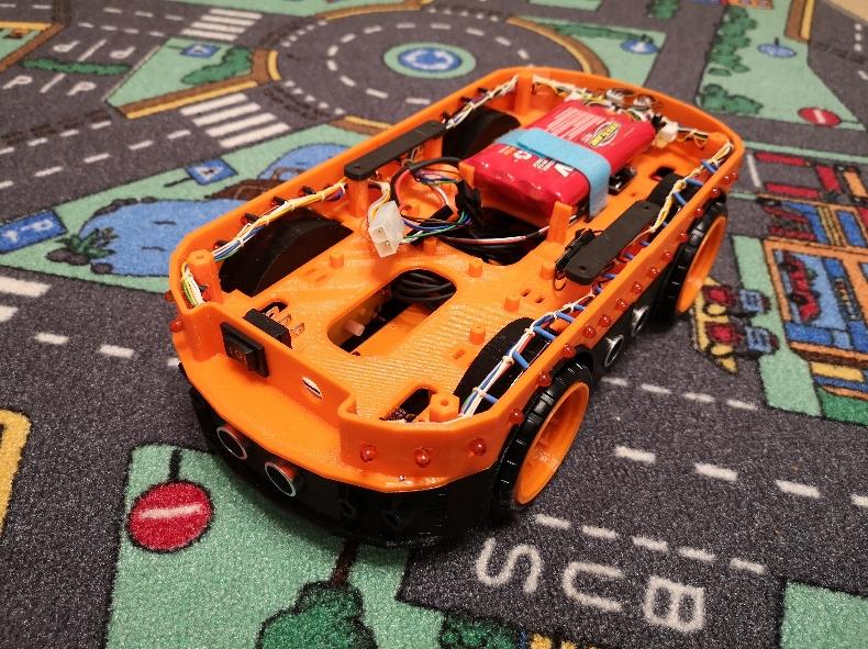
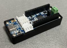
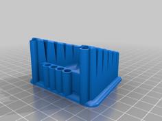
Hier finden Akku und Hauptschalter, sowie ein Anschluss zum Laden der Akkus platz. Welchen Akku ihr verwendet bleibt euch überlassen, ich verwende einen älteren 9,6V RC Akku aus 8 Zellen. Befestigen könnt ihr Ihn mit Klettband (so wie ich) oder mit Kabelbindern.
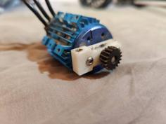
Unter dem Akku befinden sich die Gabellichtschranken für die Encoder-Scheiben der Motoren aus Level 0. Je nach verwendeter Gabellichtschranke benötigt ihr ein paar Distanzen um diese in die richtige Höhe zu heben.
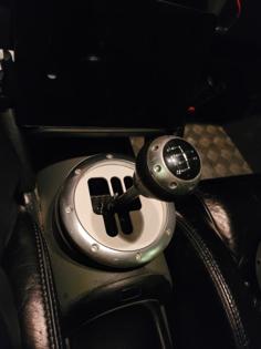
Weiterhin finden sich hier bis zu 44 Stück 5mm LEDs. Diese können für lustige Animationen oder als Debug und Status-LEDs verwendet werden. So können sie als optisches Feedback für zum Beispiel die Fahrtrichtung, den Akkustand, Warnung, Annäherung oder sonstige Zustände genutzt werden. Einzelne LEDs können dabei einzelnen Sensoren zugeordnet sein und so den Schaltzustand anzeigen. Euch fällt da schon was ein. :)
Im vorderen Teil befinden sich 24 LEDs im hinteren Teil 20. Beide Teile habe ich sowohl mit als auch ohne Löcher für die LEDs entworfen, so sind Kombinationen möglich.
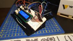
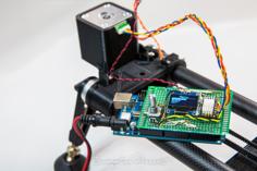
Als Ansteuerung für die LEDs verwende ich einen MAX7219CNG. Der Hardwareaufbau und das Pinout des MAX sind im Test-Sketch als Kommentare enthalten.
Benötigte Teile
MAX7219CNG
Experimentier-Platine, 10kOhm, 27kOhm, 10µF, 100nF, Stecker
0 / 24 / 20 / 44 Stück 5mm LED rot
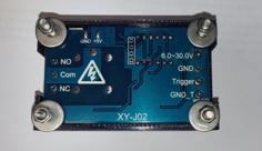
2 Stück Gabellichtschranke für Arduino
Schalter
Power-Jack
Akkupack
Wichtig
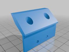
Das große Loch im hintern Teil signalisiert, dass dieser Platz frei bleiben sollte. Der Grund liegt im nächsten Level, denn dort ist der Greifer untergebracht und hier braucht es den Platz für den Servo-Motor!
Chassis - Level 0 - Drive: https://www.thingiverse.com/thing:4660593
Chassis - Accessories: https://www.thingiverse.com/thing:4669691
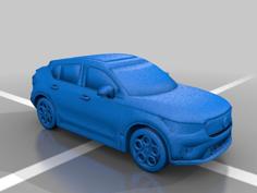
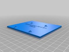
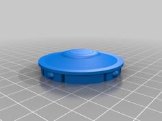
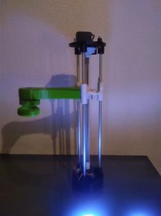
An dieser Stelle wieder die vorläufige Design-Studie:

Wenn es dir gefällt:
Hoffe jemand kann es gebrauchen.
Wenn es jemand baut, dann bitte unbedingt ein "Make" posten, ich will wissen was Ihr daraus macht!
:)
Bleibt gesund!
(Google-Translation)
It took a while, but here it is: the next level! If you do not yet know what it is about, look in the link list below for the first part (level 0) of SAMBUCCA, which explains what SAMBUCCA is. There I promised to explain in this part why I am doing this project. Well, actually you can't do that much with the finished SAMBUCCA. You can play with it, but that's about it. But the journey is the goal, as is well known, and so you learn a lot about microcontrollers, programming, circuit design, the interaction of parts, mechanics, mathematics, handling tools and software when creating this vehicle. In theory, a learning project for the desk. So it's because I want to find out if I can.
Abandonment of this level by SAMBUCCA
The battery and main switch as well as a connection for charging the batteries can be found here. Which battery you use is up to you, I use an older 9.6V RC battery with 8 cells. You can fix it with Velcro (like me) or with cable ties.
The fork light barriers for the encoder disks of the motors from level 0 are located under the battery. Depending on the fork light barrier used, you need a few distances to lift them to the correct height.
There are also up to 44 5mm LEDs here. These can be used for fun animations or as debug and status LEDs. For example, they can be used as visual feedback for the direction of travel, the battery level, warning, approach or other conditions. Individual LEDs can be assigned to individual sensors and thus indicate the switching status. You can think of something. :)
In the front part there are 24 LEDs in the back part 20. I designed both parts with and without holes for the LEDs, so combinations are possible.
I use a MAX7219CNG to control the LEDs. The hardware structure and the pinout of the MAX are included in the comments of the test sketch.
Required parts
MAX7219CNG
Experimental board, 10kOhm, 27kOhm, 10µF, 100nF, plug
0/24/20/44 pieces 5mm LED red
2 fork light barriers for Arduino
Switch
Power jack
Battery pack
Important
The large hole in the rear part signals that this space should remain free. The reason is on the next level, because this is where the gripper is located and this is where the servo motor is needed!
Chassis - Level 0 - Drive : https://www.thingiverse.com/thing:4660593
Chassis - Accessories : https://www.thingiverse.com/thing:4669691
If you like it:
Hope someone can use it.
If someone builds it, please post a "Make", I want to know what you do with it!
:)
Stay healthy!
| Runlight_Test.ino | 6.7KB | |
| SAMBUCCA_Level1_V1.5__Body_back_noLED.stl | 230.6KB | |
| SAMBUCCA_Level1_V1.5__Body_back_withLED.stl | 362.6KB | |
| SAMBUCCA_Level1_V1.5__Body_front_noLED.stl | 264.2KB | |
| SAMBUCCA_Level1_V1.5__Body_front_withLED.stl | 359.1KB | |
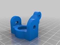
| SAMBUCCA_Level1_V1.5__Half2HalfLink_2_needed.stl | 25.5KB |