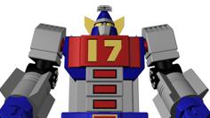
Robot With Ultrasonic Distance Measuring Sensor And Microcontroller 3D Printer Model
The file 'Robot With Ultrasonic Distance Measuring Sensor And Microcontroller 3D Printer Model' is (stl) file type, size is 277.9KB.
The file 'Robot With Ultrasonic Distance Measuring Sensor And Microcontroller 3D Printer Model' is (stl) file type, size is 277.9KB.
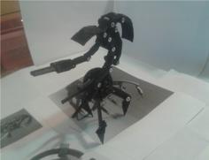
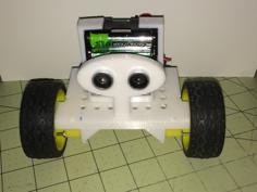
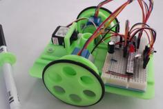
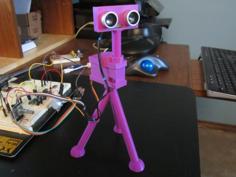
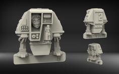
A big robot with an HC-SR04 Ultrasonic distance sensor in the eyes and a mini-breadboard with an Arduino Nano microcontroller in the body.
This is the first model I designed with electronics inside the model.
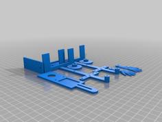
This model seems complicated with 10 STL files (and one has to be printed twice) but it's actually very simple.
The model was designed with SketchUp, Cleaned with Microsoft 3D Builder, Sliced with Cura and printed on a Robo3D R1+
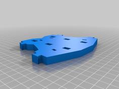
Body.stl and Button.stl should be printed with no supports, FaceOuter.stl should be printed with support everywhere, Head.stl should be printed with supports touching buildplate.
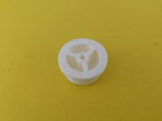
Leg.stl should be printed twice, it does not need support but a little infill helps.
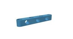
ArmLeft,stl and ArmRight.stl will both print better with a little bit of infill, supports not needed.
And finally for HeadBack.stl, back.stl and FaceInner.stl supports and infill make no difference.
FaceInner goes into FaceOuter and the HC-SR04 goes into the holes in FaceInner, it should stay in position one assembled, if it keeps falling out a little bit of hot glue will do the trick.
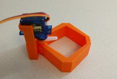
The two leds (after soldering to wires) go into the two "hears" in the Head.
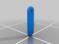
The PC switch goes into the square hole on the top of the Head, the Button covers the PC switch.
The face assembly should just slide into one side of the head.
Take the Body and cut off the three triangles holding the neck and two arms connectors.
Connect the head to the body, push all the wires from the HC-SR04, leds and switch into the neck
Now all the wires from the button, leads and HC-SR04 go into the neck and the body.
The body has a small tray for the breadboard, leave the first row (closest to the back) empty because the back has a small ledge that will hold the breadboard in place.
The left side of the body has a small hole for the Arduino's usb connector, you can rotate the left arm to hide the hole or to leave it open.
Connect the two arms and two legs
I marked this thing as "work in progress" because those are not the same STL I used, I had to re-export and fix the STLs from SketchUp, if you print this please leave a comment and tell me if everything is ok.
| Back.stl | 100.3KB | |
| Body.stl | 139.4KB | |
| Button.stl | 30.1KB | |
| FaceInner.stl | 47.4KB | |
| FaceOuter.stl | 58.3KB | |
| Head.stl | 202.4KB | |
| HeadCover.stl | 388.0KB | |
| LeftArm.stl | 40.6KB | |
| Leg.stl | 100.3KB | |
| RightArm.stl | 31.4KB |