The Quad-CPU Raspberry Pi Zero 2W is a pretty powerful beast for its size. However, if not properly cooled it will throttle its CPUs at about 80 deg C: https://raspberrytips.com/raspberry-pi-temperature/
This fan assembly helps you to push the Zero 2W to its limits, in particular if you run it at ambient temperatures above 30 deg C or apply overclocking. It fits the Zero W and the Zero as well. It offers a range of printing and fan mounting options.
Running the fan continuously is straight foward. I added an electronic temperature control circuit and associated "on/off" Python software to extend ist lifespan and reduce average prower requirements. While a heat sink isn't mandatory, it does seem to reduce the on/ff frequency due to its thermal capacity.
====================================================================
Update 20 October 2024:
I designed a more effective cooling assembly:
https://www.thingiverse.com/thing:6802831
Update 12 March 2024:
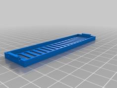
Flush countersunk screw heads in the "fan below" top plate variant give you another 1.5 mm spacing between fan and CPU to install a heat sink. Due to a CAD trick driving the slicer to make appropriate routing (see slicer pictures) you will not need supports in the screw holes. The layer height should not exceed 0.3 mm for this trick to work based on the supplied .stl files.
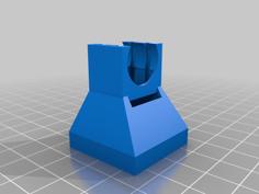
Cable guide in the "fan below / no GPIO cutout" top plate variant.
====================================================================
Depending on your preferences you have the following assembly choices:
The fan is a 5 V / 60 mA 20x20x10 mm (so called "2010") type, avilable at e.g.
https://www.aliexpress.com/item/1005002554588949.html
According to my measurements it is spinning at 12'000 RPM. You may have to shorten the leads (soldering and shrink hose required).
Apart from the 2010 fan you will require
First screw the fan either above or below the top plate with two to three M2.5 x 12 mm screws. The design assumes that the screws will cut their own thread into the top plate while you screw them in for the first time, so you don't need nuts. Depending on the tolerances of your slicer, printer and printing material you may have to widen the holes to 2 mm with the 2 mm (not 2.5 mm !) drill. Do not overtighten.
Then push the four 2.5 x XX mm screws through the top plate, the YY mm spacers and the Zero PCB. Depending on the tolerances of your slicer, printer and printing material you my have to widen the holes through the top plate and spacers to 2.5 mm.
The design assumes that the screws will cut their thread into the bottom plate. Depending on the tolerances of your slicer, printer and printing material you may have to widen the bottom plate holes to 2 mm (not 2.5 mm !). Do not overtighten.
Cut out an appropriate length from the fan leads (in my case it was 24 cm), strip the shrink tubes onto the leads before soldering, moving them away from the soldering points as far as possible to avoid shrinking them prematurely while soldering. Solder the lead ends pairwise together maintaining the color match (red to red, black to black) and isolate the soldering points with the shrink tubes by applying heat with the soldering iron or a hot-air gun.
Insert the plug over the second and third pin of the outer pin row (red wire over the second pin) for continuous fan operation. Caution: Inserting the plug over the wrong pins may permanently damage the Zero.
I implemented an "on/off" fan control circuit according to https://forums.raspberrypi.com/viewtopic.php?t=313077, see my pictures above. The Python source file "fan.py" to control the fan in "on/off" mode via this circuit is enclosed. PWM (pulse-width modulated, an alternative to "on/off") fan control is only adivisable with four-wire fans, see https://www.youtube.com/watch?v=N5h6Y7KGLDc. So far I haven't found a 2010-type four-wire fan on the market yet.
Copy "fan.py" to your "/home/pi" directory, make it executable with "chmod a+x fan.py" and add the line "/home/pi/fan.py 50 &" to "/etc/rc.local" just before "exit(0)" to automatically launch it at boot time as a background process. If configured as recommended above it will activate the fan at CPU temperatures above 50 deg C and deactivate it at CPU temperatures below 48 degrees.
Use the enclosed file "temp.py" to observe fan actvity and temperature. Copy it to your "/home/pi" directory, make it executable with "chmod a+x temp.py" and run it with "./temp.py 50" for a "fan.py" temperature limit (configured in "/etc/rc.local") of 50 deg C.
Use the enclosed file "stat.py" to observe fan on and off duration and duty cycle. Copy it to your "/home/pi" directory, make it executable with "chmod a+x stat.py" and run it with "./stat.py". No commandline parameters required.
That's it!
As always I include the OpenSCAD source file for you to adapt and/or improve:
See my other designs at
https://www.thingiverse.com/thinger13/designs
In particular:
https://www.thingiverse.com/thing:6449585
https://www.thingiverse.com/thing:5204103
| 240225_Pi_Zero_Fan_Spacers_10mm.stl | 56.3KB | |
| 240225_Pi_Zero_Fan_Spacers_14mm.stl | 56.3KB | |
| 240225_Pi_Zero_Fan_Spacers_19mm.stl | 56.3KB | |
| 240225_Pi_Zero_Fan_Spacers_4mm.stl | 56.3KB | |
| 240225_Pi_Zero_Fan_Spacers_6mm.stl | 56.3KB | |
| 240304_Pi_Zero_Fan_Bottom.stl | 85.2KB | |
| 240304_Pi_Zero_Fan_Top_Fanabove_GPIO.stl | 110.0KB | |
| 240312_Pi_Zero_Fan.scad | 7.2KB | |
| 240312_Pi_Zero_Fan_below_GPIO.stl | 228.4KB | |
| 240312_Pi_Zero_Fan_below_noGPIO.stl | 228.4KB | |
| fan.py | 1.3KB | |
| stat.py | 1.1KB | |
| temp.py | 1.3KB |