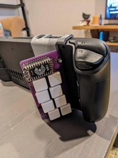
You will need:
No glue required for the case!
Switch sockets and stabiliser sockets taken from https://www.thingiverse.com/thing:4774621
Assembly:
Print:
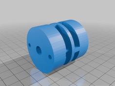
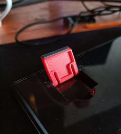
Joint OR Switch
OR
How to handwire a keeb:
https://www.crackedthecode.co/a-complete-guide-to-building-a-hand-wired-keyboard/
https://www.youtube.com/watch?v=hjml-K-pV4E
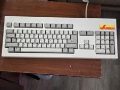
The keycaps I'm using:
https://www.mechmods.co.uk/collections/keycaps/products/pbtfans%E2%84%A2-wob-keycaps?variant=43291407319263
Insert the stabs
Insert the switches
Solder diodes to switches (black line away from the switch)
Wire up the diodes in rows and solder in place
Wire up the columns and solder in place, being careful of shorts
Wire each row and column to a pin on your controller
Insulate your controller from the switches with some tape
Cut one end off of your Micro USB cable and strip the wires
Solder the wires to the USB C daughter board
Red to VCC
Black to GND
White to D-
Green to D+
Glue the daughterboard in place in the opening in the Lower left
Use the 8mm screws on the corners and the 16mm screws for the rest of the holes.
Connect the keyboard to your computer
Pi Pico + KMK:
https://www.youtube.com/watch?v=Q97bFwjQ_vQ
Flash CircuitPython to the controller: https://circuitpython.org/board/raspberry_pi_pico/
Install KMK (drop in the 'kmk' directory): https://github.com/KMKfw/kmk_firmware
Copy on the code.py and boot.py files
Check the row and column pin definitions match what you've done on your own controller in code.py
boot.py contains the row and column number of the key to mount the storage device when held. Adjust this to the appropriate value for your wiring.
| boot.py | 952.0B | |
| code.py | 3.2KB | |
| Orthosplit_Keeb_Tilted_Lower_Left.stl | 117.5KB | |
| Orthosplit_Keeb_Tilted_Lower_Right.stl | 88.4KB | |
| Ortho_Split_Mini_Keeb_Unibody_Lower.stl | 149.4KB | |
| Ortho_Split_Mini_Keeb_Unibody_Lower_Left.stl | 88.4KB | |
| Ortho_Split_Mini_Keeb_Unibody_Lower_Right.stl | 65.2KB | |
| Ortho_Split_Mini_Keeb_Upper_Left.stl | 122.2KB | |
| Ortho_Split_Mini_Keeb_Upper_Left_No_Stabs.stl | 113.1KB | |
| Ortho_Split_Mini_Keeb_Upper_Right.stl | 122.2KB | |
| Ortho_Split_Mini_Keeb_Upper_Right_No_Stabs.stl | 112.9KB | |
| Ortho_Split_Unibody_Joint.stl | 44.2KB | |
| Switch.stl | 94.2KB | |
| Switch_with_bezel.stl | 194.6KB |