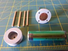
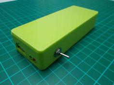
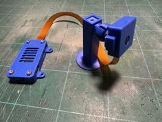
This is an OpenAPS belt clip case for a Raspberry Pi 0W with a wired/soldered RFM69HCW. The power control, battery connection, and belt clip designs are highly specific to my use case, as I designed those aspects around parts I already had laying around. However, the organization of the system and the overall concept is applicable for others to design from.
Notes on the aspects specific to me:
- The power controller was taken from a portable battery pack for other Lithium-based batteries. The batteries were bad, but but the circuitry behavior worked for a Pi running OpenAPS.
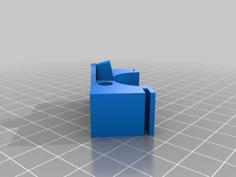
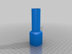
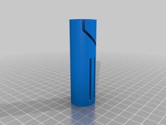
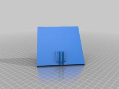
- The USB Support Spacer part is used to keep the USB C jack in the intended hole after it's placed in the body. The idea is that there's enough room in that space to slide the controller in the body, and so pushing a plug in the jack would cause it to pop out without this support piece.
- The battery contacts were taken from other battery packs for AA's or AAA's.
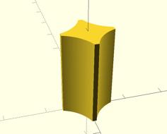
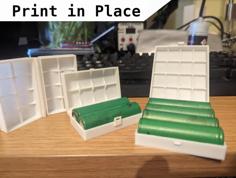
- Should the original caps be used, note that there are very small lines under each of the overhangs intended to only be support. I had a difficult time getting my slicer to add support in a way that was easy to remove in such a small space, so I opted to exclude support in those areas and designed my own.
- The belt clip was leftover from the Animas pumps I used previous to looping.
Some notes about this design:
- The system is a Raspberry Pi 0W, with a RFM69HCW soldered via connecting wires.
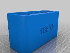
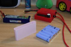
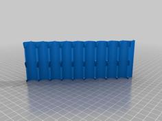
- The batteries are a pair of 18650 cells in parallel for extra run time between charges.
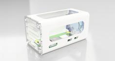
- There's a dedicated channel for holding the antenna on the RFM69HCW. The diameter is specific to the wire I used.
- There's space reserved for the micro USB plug for powering the Pi.
- The spaces for the Pi and the power controller have diamond shapes cut out for heat dissipation. In my case, it also serves for observing the status LEDs on the power controller.
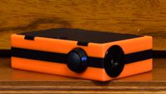
- The antenna side cap, includes a "peep hole" to see the light from power LED on the Pi.
- The same cap also includes two pairs of holes to place bare copper wires exposed to the outside of the case. These are wired and soldered to pins 5 and 6 of the GPIO to serve as the power button. This should be rarely needed, hence the lack of a real button. The main goal was to keep it low profile. Should this be needed, I just use something metal to touch the two wires together.
- The cap screws are sized for M2 x 8. I chose the screws I did from a local Ace hardware store in part due to their low-profile head.