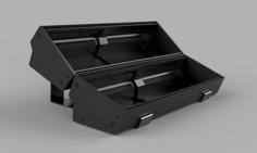
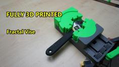
This vise is made for work with small PCB or electronics, etc. Advantage of this vise is easy print, low wobble and modular system - if something breaks, it's fast and easy to repair. You just need some metal screws, but it's basic available hardware.
Vise pitch: 115mm ; Vise width: 80mm ; Clamp pitch: 45mm.
Designed to be printed from PLA. It has low tolerances, but everything should fit well with most of printers without extra postprocesing.
I printed all the parts with 35% infill, 3 perimeters, just Rods 60% infill.
Screws
M3x10 - 4x ; M3x15 - 8x ; M5x20 - 2x (for clamp) ; Alternatively M2.5x20 - 2x for attaching Handle and Lock_ring to the Rod.
M3x15 or M2.5x20 for clamp.
Rubber pads (optional)
Use some round rubber pads 10x4mm like this (K1004).
Furniture pads (optional)
For the clamp use something round like this (20mm or 22mm in diameter).
Vise
1) Join Handle to Rod by M3x15 screw (alternatively M2.5x20).
2) Insert and attach Thread_module to Body.
3) Insert Rod to Thread_module, insert Lock_ring to Upper_slider.
4) Insert Lower_slider to Body and attach it to Upper_slider by 4x M3x15 screws.
5) Attach Rod to Upper_slider. Use M3x15 screw (socket head) or M2.5x20.
6) Attach Jaws to the vise by M3x10 screws (or M3x15).
7) Optional: Assembly and attach Clamp to the Vise. Use M5x20 screws.
8) Jaw_2.1 and Jaw_2.2 are flat jaws - optional.
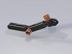
Clamp
1) Insert Slider to Body.
2) Insert Cap to Body.
3) Connect Handle to Rod.
4) Attach Rod to Body.
5) Attach Clamp to Vise.
There are 3 versions of the Slider.
* Flat - flat head.
* Round 20mm - head for round pad Ø 20mm.
* Round 22mm - head for round pad Ø 22mm.
- First print 1/4 of Rod and Thread_module to try, if it fits. If not, just scale Rod in slicer in X,Y axis by 1% and try it again.
- Set Z-seam in slicer to random when printing Rod, Thread_module.
- Use socket head screw for Rod and Lock_ring.
- Tighten the screw into the Rod before assembling the vise. If it is too hard, use M2.5 screws or carefully drill it a bit.
* 30.5.2021 - Releasing Vise mk1.
* 30.6.2021 - Started working on new Rod + ThreadModule with higher pitch.
* 1.7.2021 - Added assemble video.
* 1.7.2021 - Added Slider_clamp_V2 for higher clamp pitch.
| Body.stl | 3.6MB | |
| Body_clamp.stl | 238.4KB | |
| Handle.stl | 2.6MB | |
| Handle_clamp.stl | 687.0KB | |
| Jaw_1.1.stl | 38.2KB | |
| Jaw_1.2.stl | 38.0KB | |
| Jaw_2.1.stl | 33.7KB | |
| Jaw_2.2.stl | 33.7KB | |
| LockRing.stl | 138.5KB | |
| Lock_clamp.stl | 7.7KB | |
| LowerSlider.stl | 240.1KB | |
| Rod.stl | 3.6MB | |
| Rod_clamp.stl | 1.6MB | |
| Slider_clamp_20mm.stl | 117.7KB | |
| Slider_clamp_20mmV2.stl | 159.4KB | |
| Slider_clamp_22mm.stl | 119.0KB | |
| Slider_clamp_22mmV2.stl | 160.7KB | |
| Slider_clamp_flat.stl | 89.3KB | |
| Slider_clamp_flatV2.stl | 130.8KB | |
| ThreadModule.stl | 2.7MB | |
| UpperSlider.stl | 4.0MB |


![[BLADE][HUE] Sync 3D Printer Model](https://cdn.3axis.co/assets/5e/fe/f5/73/5efef573-ae33-4cc8-a39b-e57776799cdd/images/20f2247b-9dc3-48e6-ab9e-3f4099226693_thumb.jpg)