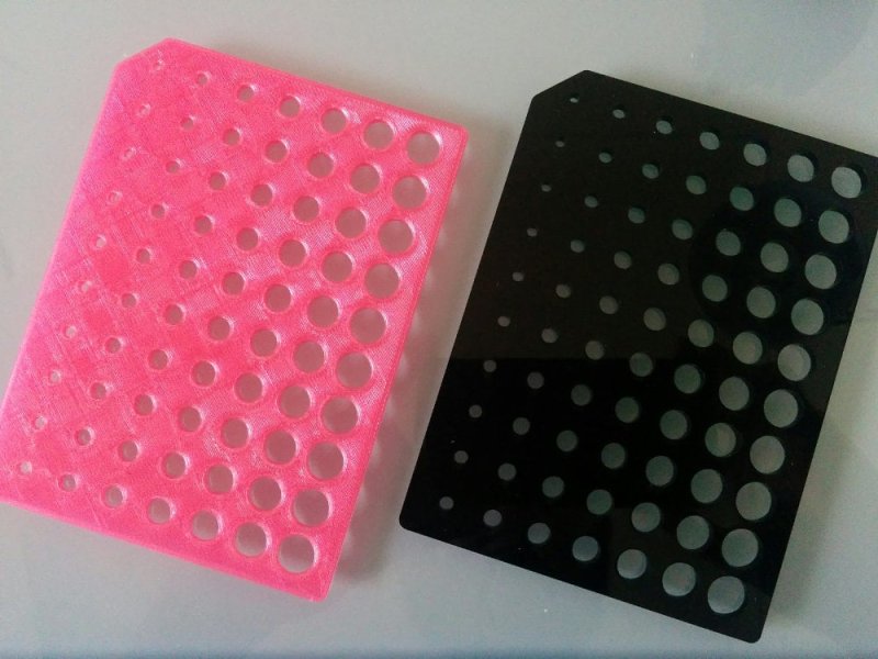
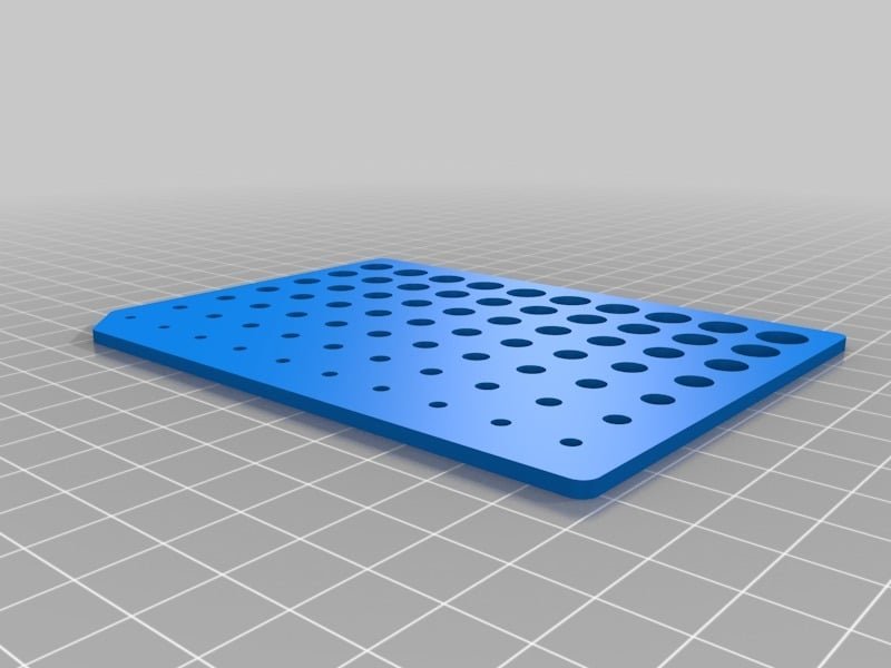
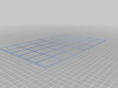
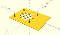
This is a plate designed to print every hole from 2.0mm to 8.9mm in 0.1mm increments.
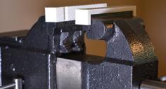
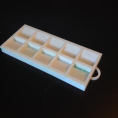
Pictured are a 3D printed version (pink) and an acrylic laser cut version (black).
The cutout orientation corner is the top left. Holes increase from 2mm to 8mm across, and increase from +0.0mm to +0.9mm down.
This is intended to test clearance for metric screws, so you know how accurate your printer/cutter is at making various size holes, and so you can test with real screws you already own and design your part so the screws fit.
Some might consider this better than say designing a 3mm hole, having it print at 2.5mm, and drilling the hole out to fit an M3 screw.
Note that you aren't supposed to print/drill/cut holes exactly to the thread size they hold. Look up "metric thread clearance" on Google and you'll see the recommended size for a metric thread is always slightly larger than the actual thread.
OpenSCAD file is included so you can modify as desired.
Requires scad-utils from https://github.com/openscad/scad-utils
It's a 2D design extruded vertically so you can also export as a DXF for laser cutting.
It's mostly scripted with variables so you could probably make this into a Customizer with minimal effort.
License is CC-BY-SA so please share your remixes for the benefit others.
| Metric_Screw_Clearance_Calibration_Plate.scad |
| Metric_Screw_Clearance_Calibration_Plate_85x115x2.4.stl |