Welcome to my first posted thing. More to come when I have time to revise designs, and write more of these summaries.
The updated right side piece has been posted, but has not been tested for fitment. If you print it use with caution. I will print it and test it in the next couple days
I designed this upgrade based off of a schematic derived from the I3V12" Prusa CAD file which somebody took the time to import from Colin's laser cutter file. So who ever was responsible for that, thank you for saving me some measuring!
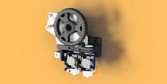
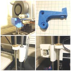
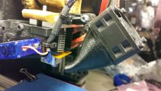
The first time I printed this (and likely the last time for me.) I had to remove material from the posts to make them fit in my frame with a Dremel. Even still I had to press them in pretty hard. To save you some time and elbow grease I removed 0.5mm from each interference to help the tolerance, but you may still have to take away some material with a rotary tool. This happened because I didn't account for the laser cutter kerf from the original design. That said, once installed my Z-axis lead screws have kept much better synchronization than they ever did with the original threaded rod. You might notice I don't have a M3 installed on the right side Z motor mount. That's because I literally had to melt and hammer the plastics together for mine, and the holes were undersized. You should not have to do this as I adjusted the hole size, and the tabs.
Mine is installed on the I3V 10" but I would imagine that it could be installed on many of the Maker Farm kits.
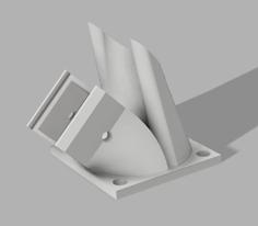
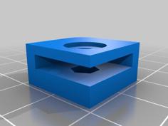
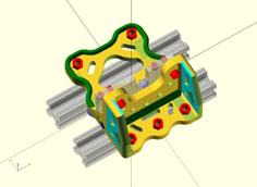
You will need to print four of the side supports, two flanges, and two motor mounts.
Required hardware:
-Lead Screw (This is the one I used - https://www.amazon.com/gp/product/B017AR5QBS/ref=oh_aui_search_detailpage?ie=UTF8&psc=1)
400 Zsteps/mm (1/16ths microstepping drivers, and 200 step/rev motors.)
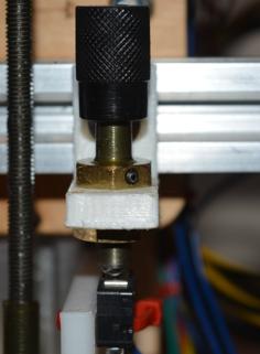
-5mm to 8mm Coupler (Again the one I used - https://www.amazon.com/gp/product/B00KHTVOEU/ref=oh_aui_search_detailpage?ie=UTF8&psc=1)
Other hardware should work, but this was designed for an 8mm rod with a nut like the one on that threaded rod.
All the other required hardware is re-used from the original brackets.
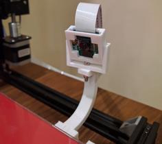
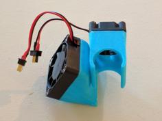
The only things that are a little less than optimal, the X-axis idler has to be sanded on one side to stay in the retaining hole (this is getting redesigned,) and the belt rubs the back of the left flange a little bit. But, I have had no problems with it. I am planning to design a new carriage to fix the rubbing. The idea was for a front and rear plate to aid rigidity and line up the belt with the center of the rail, has active cooling, illumination, and dual bowden extruders. It will still retain a modular approach for those who don't want a bowden setup. I just want more print speed and less vibration, but I know bowden has it's own drawbacks.
The other modification you will need to make is cutting down the 4 bolts that held the nut for the threaded rod (or just buy new ones.) I just did this by eye, but from measurement the shank of the bolt should be just under 9mm to keep from bottoming into the v-rail.
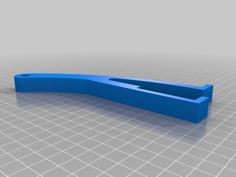
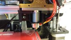
The brackets press into the X-axis rails. Mine popped in with a little tension, which is where I wanted it. My printer is pretty well calibrated, so pint that part first and make sure it fits in your rails!
Side note, please excuse the messy hot glue on the print cooling fan... Working on updates :P
| Flange.stl | 147.8KB | |
| Flange_Right.stl | 220.1KB | |
| Motor_Mount.stl | 82.1KB | |
| Side_Support.stl | 46.2KB |