I have a very old metalworking lathe (Zyto) made in the 1930s/1940s, and it didn't come with graduated dials on any axis. I made some a while ago but they weren't too great, so now I plan to make some decent ones. Unfortunately I don't have any sort of dividing equipment for cutting the graduations accurately.
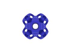
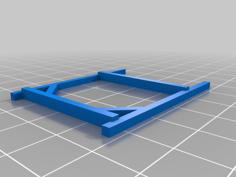
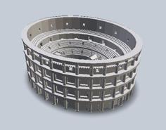
This inspired me to design this division plate, which is fixed to the lathe's chuck backplate using the chuck's mounting screws (I actually needed slightly longer screws). The rest of the mechanism will locate on the division plate's peg holes to lock the spindle - this is still in the design phase so I will publish that later (basically, it's an arm with a spring-loaded peg that fits into the holes at each position, fixing the lathe spindle in 1 position at a time).
The dimensions of this plate, and the upcoming mechanism, are very lathe-specific; I am only publishing it so that others may use it as the foundation of their own designs. The STL files I have included are for my lathe; you will almost certainly have to change the OpenSCAD variables to suit your own needs, then create your own STL files.
The peg holes should be in multiples of 5 - I needed one disc with 100 holes and one with 125 holes. In my case, this is for lead-screws of 10 turns per inch and 8 turns per inch, respectively. Other values will work, but the 5 & 10 marker dots may look strange!
These dots are placed within the peg hole circle to help with counting: three dots indicate the starting position (which is also a 10), 2 dots indicate the 10s, 1 dot indicates the 5s. This was intended to aid me when engraving the dials - long strokes for the 10s, shorter for the 5s, shortest for the 1s.
This plate is not designed for heavy-duty work - it's really quite fragile in machining terms - but perfectly suited for graduating a number of dials made from aluminium or brass.
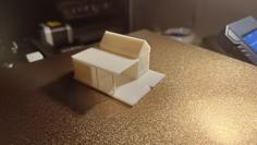
The code can generate a test plate that can be used to check the fit on the back of the chuck - it compiles a lot quicker in OpenSCAD and also uses a lot less plastic.
If you make your own division plate, DO check that you have the correct number of peg holes before committing to a new project! Mine turned out OK every time, but it really would be a pain if you started a job and found that the count was wrong when you get to the end.
If you plan to fix your plate to the back of the chuck as I have done, do not run the lathe at any significant speed as it has not been designed with rotary forces in mind - the plate may burst unexpectedly, throwing sharp pieces everywhere. I cannot predict the speed at which this may happen! My plan is to machine the part as normal until it's ready for engraving, then I'll remove the chuck and its backplate as a unit, fix the dividing plate, refit the chuck/backplate and then do the markings when the lathe is switched off.
| division_plate.scad | 3.1KB | |
| division_plate_100.stl | 3.0MB | |
| division_plate_125.stl | 3.7MB | |
| division_plate_test.stl | 289.3KB |