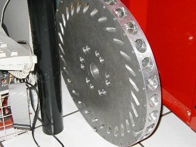
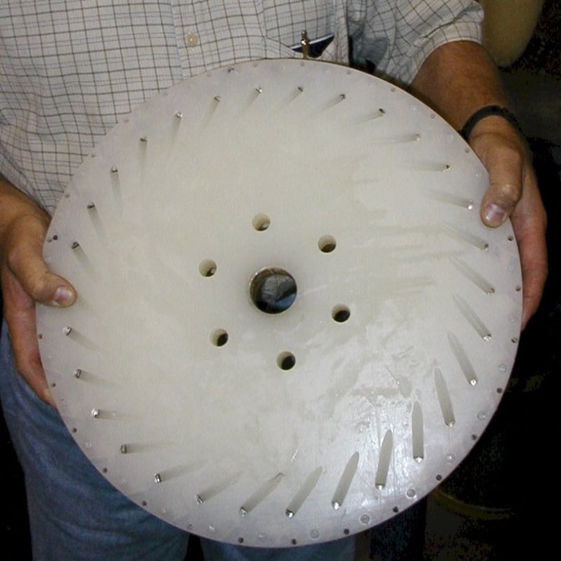
Do research on the Perendev Magnet Motor {Note: All files are contained in the .rar file} Wether it works or not as is, this is a starting platform for development. Updated Information from http://www.callowayengines.com/msg18.htm " The Perendev motor is claimed to be in the repel mode for proper operation. We question this claim with results of our own experiments. After watching the Perendev video numerout times, we notice that the clam shells in the video more or less just fall right in to the rotor group. We also notice that jacking the clam shells away from the rotor group causes a jerking or pulsing action of the clam shell group as if it is in attraction to the rotor group. From our experiments, I cannot get the clam shell group to close in on the rotors very easily in the repel mode. There is no jerking when the shells leave the rotor group either. They just push apart rapidly in one smooth action. Now, when we setup the unit in the attraction mode we get the same looking results as the Perendev video. But, our unit does not rotate with the measurements we are presently using. Our stator group is not built correctly. The hole spacings are incorrect. We would like to pass on a experiment we have had success with using a track we built. Thjs seems to show the correct measurements needed for a trial run of the motor in attraction. Because of health insurance premiums and being retired on a fixed income, we are taxed out here to build the new stator group with different hole spacings for now. Perhaps someone out there can give it a try. The rotor group holes should be .875 in diameter with 0.4375 spacings. This would give a measurement of 1.3125 from center to center of each rotor bore. The stator group holes should be .875 in diameter with .875 spacings. This would give a measurement of 1.750 from center to center of each stator bore. Your rotor group will have to be large enough in diameter to support 30 degree angles using a bore depth of 1.500. A large rotor diameter will have to be used with 30 degree angles at the required depth because of interference problems that arise between bores. Then build the stators to match the rotor group. You must use a magnet length of at least 1.500 in the rotor and stator groups. Longer would be preferred. If you don't, it will fail. You can stack magnets to obtain this minimum length. If you use a shorter length of magnets, shields around the magnets MUST be used. Shields can also be used with the minimum required length of magnets also, which would help by isolating the repel field away from the squeezed flux in the rotor group. The magnets will be setup in the attraction mode from stator to rotor. Such as: All South poles out in the rotor and all north poles out in the stator. IMPORTANT!!!!!!! PUT MAGNETS IN EVERY HOLE IN ROTOR GROUP. SKIP EVERY OTHER HOLE IN STATOR GROUP. There are very important reasons holes are skipped in the stator group. This gives a relaxation time for rotor magnets. It allows the rotor group to be more directional. It weakens flux attraction from previous magnets just passed. We made a board track here to test these measurements and it works very well. The question is....Will it work in a Perendev design without using PFI? I don't know. We hope maybe someone out there will try, and let us know your results. UPDATE: Some do not understand the Perendev method. I will try to explain. A large magnet size may help me get my point accross. Lets take a couple of regular cylinder magnets of say: 2" diameter X 3" long. The flux comes straight out the end of the magnet and curves back to the Bloch wall (some to the other pole) in a mushroom pattern. The exact center of the magnet pole end face is the strongest magnetic flux point on the face of the magnet and slightly weakens to the edges of the face (because of vortex spin). Now, if we wrap the end of the magnet (not the face) with ferrite or of the equivalent this weakens the flux effect in the surroundinh mushroom flux area of the magnet pole. THEN we can angle the magnet and have a differential flux reading (because of angle) to a attracting or repelling magnet. The angle closest to another magnet will be stronger than the wide angle of the magnet. This will not be as effective if we don't surround the magnet with ferrite. The magnetic flux field is contracted and absorbed (not weakened) using this method. The effect is more noticeably seen with larger diameter magnets using angles (more distance across the face). Magnetic flux can extend out from a magnet pole further than you may think in a distorted manner. But the ferrite pulls and contracts the field inwards in a more uniform manner so that a difference in flux density can be seen from one side of the magnet face to the other when angled. When you set this up in a Perendev design, you got yourself one powerful motor. (Plus the magnets will last in the attraction mode) So, don't think about shielding when it comes to magnets. Think about how you can conform and contract the flux field in a more predictable uniform manner using ferrite. Then you will have a good magnetic flux differential across the face when the magnet is angled. After all, flux differential (strong on one side and weaker on the other side) across a magnetic face is all that is required to make a good track or engine. This can all be seen using magnetic film." https://www.youtube.com/watch?v=PFGiWiXMHn0 http://vimeo.com/105081072 https://www.youtube.com/watch?v=74bXfwlEH0Y https://www.youtube.com/watch?v=wq5-ZDFkF2g https://www.youtube.com/watch?v=fqJDrFMqGlU https://www.youtube.com/watch?v=2CbaneW7qD8 https://www.youtube.com/watch?v=8hznJB0S0Jc https://www.youtube.com/watch?v=yVSMAks7aEc https://www.youtube.com/watch?v=IwXwEL3ZC_o https://www.youtube.com/watch?v=i3uvql2YE6U https://www.youtube.com/watch?v=-ASVe4gOjew http://fdp-energy.com/perendev/default.asp http://freeenergynews.com/Directory/Perendev/MagneticMotor/index.html http://www.energeticforum.com/renewable-energy/963-anyone-tried-build-perendev-motor.html Supplemental information on Magnetic shielding spacing and overcoming the "sticky spot" https://www.youtube.com/watch?v=HiI22CdBbv4 https://www.youtube.com/watch?v=tNenBYxoYq0 https://www.youtube.com/watch?v=-Aqu9f1KbqE https://www.youtube.com/watch?v=KhY7hHb2l6o 1 streamlined video https://www.youtube.com/watch?v=HzuIjudmqac


