English version below
CHECK out my new basic design
https://cults3d.com/de/modell-3d/spiel/hardware-w-o-brass-inserts-snap-fit-design-for-a-diy-steel-darts-scoring-syst-ckndlhc
Hardware für ein DIY steel darts scoring system (z.B. ähnlich autodarts, wedart, dartit)
Komplette Überarbeitung des ursprünglichen Designs (altes Design zu finden in der Archive.zip Datei)
Erweiterte kostenpflichtige Version mit 40° Ringsegmenten (Drucken auf Druckbettgrößen 256 mm x 256 mm möglich) und 60° Ringsegmenten (Design-Update in KW22)
https://cults3d.com/de/modell-3d/spiel/erweiterte-hardware-fuer-diy-steel-darts-scoring-system-autodarts-wedart-darti
UPDATE 05.08.24:
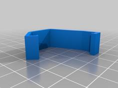
Montagehilfe für Systeme ohne Grundplatte an der Wand. Montagehilfe wird in den Fuss geklippt und zentriert sich über den Abstand zum Board. Datei: "optional_assembly_aid.stl"
Am besten zuerst die Dartscheibe montieren, dann nur den Fuss über der Zahl 6 oder 11 mit Hilfe eines waagerechten Strichs anreißen. Anschließend System zusammenbauen, den einen Fuß montieren und die beiden anderen Füsse anreißen. Anderere Vorgehensweise natürlich auch möglich.
UPDATE 24.07.24:
-Bearbeitung der Auflage der Kameraabdeckung(cam lid).
-Einfügen eines Bajonett-Verschlusses für das Anbringen eines Kameraschutzes, etc.
-Beide Änderungen kompatibel mit alten Versionen
-Target Corona Adapter hinzugefügt, jetzt auch zusammen mit dem zweiteiligen Fuss von meinem System verwendbar
Bitte 6 x Schrauben M4x16 benutzen
- Fuß-Adapter für Umstieg auf dieses System (Fuss mit "old school" Bohrungsabstand [ca. 73mm und ca. 22 mm]), Kabelabgang nach hinten. Bezeichnung: "optional_old_school_cam_arm_lower_part.stl"
-größerer Kabelkanal
-größere LED-Bohrung bei einteiligem Fuß>>Montage des 12V-LED-Bandes jetzt durch die Bohrung möglichdeshalb wurde die Höhe des LED-Rings geändert, da die Gewindeeinsätze für den LED-Ring sonst zu wenig Material hätten
Falls Interesse an der Hardware besteht und kein Drucker zur Verfügung steht, mich einfach anschreiben, ich kann sowohl die Hardware drucken, als auch eine Grundplatte fräsen (DXF in der kostenpflichtigen Version) und verschicken. Bei Hardware-Bestellungen sind alle erforderlichen Teile (Schrauben, Gewindeeinsätze, Kabelbinder) enthalten.
.
Kommunikation gerne über discord
Name: CKNdlHC
Das Design hat folgende Besonderheiten:
**- Kameraarm nach Wunsch entweder 1-teilig oder 2-teilig möglich, weitere Längen in der kostenpflichtigen Version
- Der 1-teilige Kameraarm kann jetzt auch mit Druckbettgrößen 256 mm x 256 mm oder größer gedruckt werden (z.B. mit Bambulab-Drucker oder Neptune4 Plus/Max, etc.)
-Lichtring im Stecksystem, der Ring wird analog eines Puzzles oder Kindereisenbahnschienen gesteckt, siehe Fotos. Eigentlich wäre hier keine Verschraubung mehr nötig.
Bitte zuerst die Datei „Slicer_test“ slicen und drucken und testen, ob die Ringsegmente sauber zusammen passen.** - LED-Kabel kann zusätzlich in den 1-teiligen Kameraarm „versteckt“ oder durch den Fuß geführt und entlang des Rückens geführt werden.
- 2-teiliger Kameraarm trennbar an der LED-Kabel-Durchführung (oberer Teil kann im Nachhinein durch einen längeren Arm ersetzt werden.)
- Nutzung mit 28mm x 28mm-Platinencams (OV9732, IMX179, etc.)
- 30° Segmente für Lichtring [40° und 60°-Segmente bei Druck bis zu 17% schneller gedruckt. Ausserdem stabiler (weniger Teile) als 30°-Segmente >> 30° und 40°-Segmente in meinen anderen Design zu finden]
- Höhe der Lichtringverschraubung ist auf 195 mm eingestellt
- Klebezone für LED-Lichtstreifen leicht angewinkelt (21°)
- Höhe Kameraarm: ca. 299,5 mm
- Gesamthöhe des Systems: ca. 322 mm
- Linsenposition-1: Höhe ca. 282 mm
- Linsenposition-2: Höhe ca. 305 mm
- Ø des Hilfskreises: ca. 750mm
Folgende Teile müssen für ein vollständiges Setup gedruckt werden:
- 3 x „cam_arm_regular“ oder je 3 x „cam_arm_lower_part” und je 3 x “cam_arm_upper_part_281_mm” oder eine Mischung von beiden (z.B. um das LED-Kabel einfacher zu verlegen: 2 x „cam_arm_regular“ und 1 x „cam_arm_lower_part”+ “cam_arm_upper_part_281_mm“)
- entweder 3 x „cam_lid“ oder „cam_lid_vent“, je nach Wunsch
- 3 x “30°_ring_cam_mount“
- 9 x “30°_ring_intermediate“
Folgende Bauteile werden zusätzlich zu den Druckteilen benötigt:
Gewindeeinsätze:
Schrauben (DIN 912):
6 x M4 x 10 mm: Befestigung Arme mit Ring + bis zu 6 x M4 x 10 mm weitere Schrauben für die Befestigung der zweiteiligen Variante
insgesamt mindestens 6-12 x M4 x 10 mm Schrauben
12 x M4 x 16 mm: Befestigung Füße in Grundplatte + 12 x M4 x 16 mm; Befestigung der Ringsegmente
insgesamt 24 x M4 x 16 mm Schrauben
- Insgesamt 12-24 x M2 x 6mm Befestigung Deckel-Gehäuse und Gehäuse-Kamera
Affliate Links:
LEDPRO LED Strip 6000k:
https://amzn.to/49yYjjM
Klebeband für besseren Halt:
https://amzn.to/3xqtXCW
COB-LED 6000k (noch nicht im Betrieb getestet):
https://amzn.to/3UbxYUo
Basiert in den Grundzügen auf viperman3s-design:
https://www.thingiverse.com/thing:5545019
https://cults3d.com/en/3d-model/game/dartboard-led-ring-and-camera-mount-v2
Hardware for a DIY steel darts scoring system (e.g. similar to autodarts, wedart, dartit)
Complete revision of the original design (old design can be found in the Archive.zip file)
Extended fee-based version with 40° ring segments (printable on printer sizes of 256 mm x 256 mm) and 60° ring segments(design update in cw22)
https://cults3d.com/de/modell-3d/spiel/erweiterte-hardware-fuer-diy-steel-darts-scoring-system-autodarts-wedart-darti
UPDATE 8/5/24:
Mounting aid for systems without a wall base plate. The assembly aid is clipped into the foot and centers itself over the distance to the board. File: "optional_assembly_aid.stl"
Mount the dartboard first, then only mark one foot above the number 6 or 11 using a horizontal line. Afterwards assemble the system and mark the other two feet. Of course, other sequences also possible.
UPDATE 24.07.24:
-Editing of the cam lid overlay
-Insertion of a bayonet lock for attaching a camera guard, etc.
-Both changes compatible with old versions -
Added Target Corona adapter, now also usable together with the two-piece foot of the system Please use 6 x screws M4x16
- Foot adapter for switching to this system (foot with "old school" bore spacing [approx. 73mm and approx. 22 mm]), cable outlet to the rear. Description: "optional_old_school_cam_arm_lower_part.stl"
-larger cable duct -larger LED hole with one piece foot>>mounting of the 12V LED strip now possible through the hole changing of the LED ring height, as the threaded inserts for the LED ring would otherwise have not enough material
If you are interested in the hardware and no printer is available, just write to me, I can print the hardware as well as mill a base plate (DXF in the paid version) and send it to you. All necessary parts (screws, threaded inserts, cable ties) are included with hardware orders.
**Communication via discord
Name: CKNdlHC**
The design has the following special features:
-Camera arm can be either 1-piece or 2-piece as required, longer lengths available in the fee-based version
-The 1-piece camera arm can now also be printed with print bed sizes 256 mm x 256 mm or larger (e.g. with Bambulab printers or Neptune4 Plus/Max, etc.)
-Plug-in based light ring system, the ring is plugged in like a puzzle or children's train tracks, see photos. No screw connection would actually be necessary here.
Please first slice and print the file "Slicer_test" and test whether the ring segments fit together properly.
- LED cable can also be "hidden" in the 1-piece camera arm or routed through the base and along the back.
- 2-part camera arm can be separated at the LED cable feed-through (upper part can be replaced later with a longer arm).
-Use with 28mm x 28mm board cameras (OV9732, IMX179, etc.)
-30° segments for light ring [40° and 60° segments printed up to 17% faster. Also more stable (fewer parts) than 30° segments >> 30° and 40° segments can be found in my other designs]
-Height of the light ring screw connection is set to 195 mm
-Adhesive zone for LED light strips slightly angled (21°)
-Camera arm height: approx. 299.5 mm
-Total height of the system: approx. 322 mm
-Lens position 1: height approx. 282 mm
-Lens position-2: Height approx. 305 mm
-Ø of the auxiliary circle: approx. 750 mm
Following parts must be printed for a complete setup:
- 3 x „cam_arm_regular“ or 3 x „cam_arm_lower_part” und je 3 x “cam_arm_upper_part_281_mm” or a mixture of both (z.B. to have an easier LED cable laying: 2 x „cam_arm_regular“ and 1 x „cam_arm_lower_part”+ “cam_arm_upper_part_281_mm“)
- either 3 x „cam_lid“ or „cam_lid_vent“, as required
- 3 x “30°_ring_cam_mount“
- 9 x “30°_ring_intermediate“
The following components are required in addition to the printed parts:
Threaded inserts:
-6 x M4 threaded inserts for melting: mounting ring-arm, mounting arm-housing camera
-Up to 6 additional M4 threaded inserts are required when (also) using the 2-part arm
-30° ring: 12 x M4 threaded inserts for melting in
A total of at least 18-24 x M4 threaded inserts
-min. 12 x M2 threaded inserts for melting in: Fastening cover housing and housing camera; 12 threaded inserts are sufficient, but 24 inserts can also be melted in.
At least 12-24 x M2 threaded inserts in total
Screws (DIN 912):
-6 x M4 x 10 mm: Mounting arms with ring + up to 6 x M4 x 10 mm additional screws for mounting the two-part version
A total of at least 6-12 x M4 x 10 mm screws
-12 x M4 x 16 mm: Fastening feet in base plate + 12 x M4 x 16 mm; fastening the ring segments
24 x M4 x 16 mm screws in total
Total of 12-24 x M2 x 6mm fixing cover-housing and housing-camera
Affliate links:
LEDPRO LED Strip 6000k:
https://amzn.to/49yYjjM
Adhesive tape for better hold:
https://amzn.to/3xqtXCW
COB-LED 6000k (not yet tested in operation):
https://amzn.to/3UbxYUo
Basically based on viperman3s-design:
https://www.thingiverse.com/thing:5545019
https://cults3d.com/en/3d-model/game/dartboard-led-ring-and-camera-mount-v2



![Camera Mount [Long Arm_no Clamps Required] For Target Corona LED Light Darts 3D Printer Model](https://res.3axis.co/dfeae141-b72f-4f71-8a01-092516da62b5/images/5ac1cf83-dfb1-4689-8ab7-aba078368a72_thumb.jpg)
