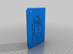
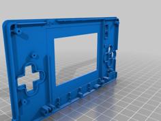
Gameboy Macro Faceplate
This project was done in July 2020, I haven't modified the files since then and decided to upload them here.
Note: in the picture an earlier version is shown where the Start/Select cutout is different from the one in the stl file. The new one allows easier access to the buttons.
The goal
Make a faceplate for the Nintendo DS Lite that allows modding it into a Gameboy Macro without any modification to the shell and allowing the use of stereo speakers.
At first I wanted this mod to use no additional screws than the ones from the DS Lite but unfortunately after more than 10 iterations and attempts and several tests in different filaments I was never able to make a model that reliably produced good threads with the tiny plastic screws of the DS Lite. For this reason, the longer screws are replaced with M2x8mm screws accompanied by M2x3x3mm threaded brass inserts.
It achieved the goal of needing no shell modifications but some extra hardware is required.
A second version was originally planned where I tried to get rid of the faceplate cover and use very slim speakers between the PCB and faceplate. Unfortunately I never finished it.
Parts needed
Required print:
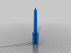
- 1x Faceplate.stl
- I used eSun ABS+ for the faceplate, for better threads using the original PCB screws. I suggest using PETG if you have trouble getting the screws to hold securely onto a PLA print.
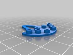
- 1x Faceplate_cover.stl
- Any filament should do for the faceplate cover, the one in the picture is in PLA
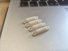
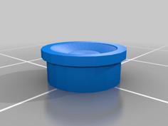
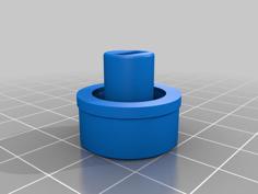
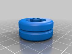
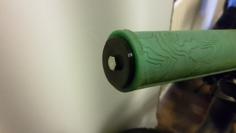
- 5x M2Spacer.stl
Required Reused Hardware:
- 1x Top screen acrylic cover
- 3x Philips head plastic screws from Bottom shell
- 1x Tri-wing head plastic screw from Cartridge slot
Required New Hardware:
- 2x Nintendo Switch speakers (AS02008MO-R)
- 5x M2x8mm screws
- 5x M2x3x3mm brass inserts
- 1x 330ohm 0805 SMD resistor
- Small enamel wires for speakers
- Hot glue to secure wires to printed parts
- Kapton tape to secure wires to pcb
Optional:
- Pieces of very thin foam to put in front of the speakers
- Reuse the Wifi antenna (see pictures)
- Glue a stylus in the bottom shell to cover the stylus hole
Rough instructions
Before anything, you'll need at least to solder the 330ohm resistor as mentioned in the original guide
Test fit all the button holes and enlarge them as needed with drill bits and utility blade if your first layer had a bit of squishing, although the model should have enough clearance.
As this mod was done a while ago (over 3 years ago at the time of writing this), the instructions may be imprecise and I apologize for it.
Instructions:
- Preparing the Hardware:
1.1. Remove the acrylic screen cover from the top screen, it will be sandwiched between the faceplate and faceplate cover to protect the screen
1.2. Remove the digitizer from the bottom screen to improve visual clarity
1.3. Remove the Wifi antenna from the top screen if you want to keep that functionality
1.4. Remove the stylus channel cover from the bottom shell - Preparing the printed parts
2.1. Add threaded inserts to the faceplate cover using a soldering iron or a dedicated tool for this task
2.2. Place the top screen acrylic cover in the groove in the faceplate cover
2.3. Place the Speakers in the grooves in the faceplate cover Note: You do not need to use the adhesive but you can. Also this is where you should add the thin pieces of foam if you want the speakers to not be visible through the grill at the front.
2.4. Cut off the support in the D-Pad hole with a flush cutter (They are there to make printing first layer easier)
2.5. Place the faceplate on top of the faceplate cover, using the posts where the threaded inserts are for alignment
2.6. In the bottomshell, thread all 5 M2 screws through the holes and put the printed spacers on the other side. They should stay in place with friction for now - Wiring
3.1. Solder the thin wires to the speakers and route them in the channels in the faceplate. Use small dabs of hot-glue to secure them to the printed piece, make sure to flatten or remove any excess as it will interfere with the PCB.
3.2. With the PCB above the faceplate like shown in the pictures, solder the wires to the test pads SPR0 and SPL0, as well as the speaker ground on the audio jack. Note: keep the wires to a minimum length but ensure you can still fold the wires to put the PCB on top of the faceplate.
3.3. Insert the face buttons and their membranes into the faceplate
3.4. Connect the screen to the PCB and fold this whole assembly over onto the faceplate, make sure the screen falls into the groove.
3.5. Secure speaker ground wires to the PCB with kapton tape, following the path shown in the pictures
3.6. Using the original mounting screws, mount the PCB to the faceplate (the holes marked with a white circle around them on the PCB
3.7. Connect the Wifi antenna, loop the wire around the Wifi module and place it above the headphone jack as shown in the pictures. - Closing it all
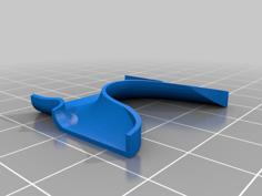
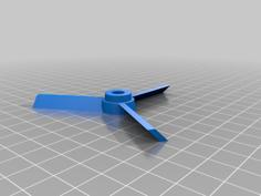
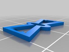
4.1. Install the bumper buttons into the faceplate. Note: I remember the small springs being very annoying to work with, be careful they don't fly off. The small fork near the pivot hole is to grab onto the spring
4.2. You can glue a stylus in the bottom shell to cover the stylus hole
4.3. Move the bottom shell on top of the faceplate and PCB assembly and deposit it over it.
4.4. Screw all M2 screws into the brass inserts
4.5. Screw the black tri-wing screw into the cartridge hole, be careful to not apply too much force and stop when the screw head bottoms out.
4.6. Put back the battery in and close the battery compartment
4.7. Insert the small rubber feet over the M2 screw holes next to the bumper buttons - Finishing touches
5.1. You can natively replace the charging port with a USB Micro port, the pins align perfectly if you break off the middle data pins and only keep the side 5V and gnd pins. Even the anchor points line up with solder pads.
5.2. Add a bit of hot-glue to the status indicator holes to diffuse the lights