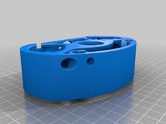
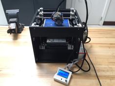
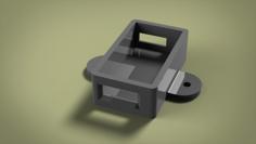
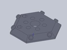
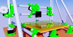
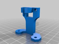
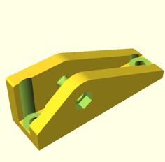
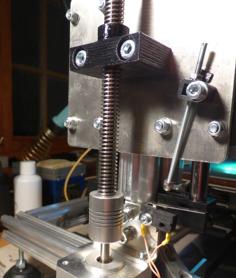
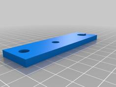
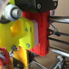
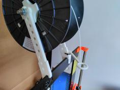
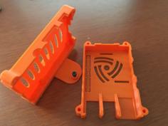
Custom design of the Anycubic I3M Z(X) axis, aiming to solve to most severe design & construction problem of this printer: the weak, wobbly, flimsy original Z(X) axis.
This modification adds a clear visual upgrade to the 3d prints - the printing quality becomes comparable to the (legendary...) printing quality of the original Prusa printers. Of course a decent extruder is required too - e.g. the BMG clone I use on my Bowden machine looks able to handle the tasks.
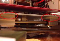
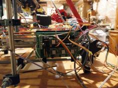
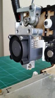
The axis is fully compatible with the original Anycubic 50mm X-gantry system and can be used for any Anycubic I3M original or customized configuration - original X carriage or customised X-carriage, with cable chain or not, with extruder fixed on Z axis (original design), on top of the frame or direct drive. Pictures show these various configurations, sometimes mixed together.
The RHS carriage has a built in, very effective belt tensioning system, solving another missing feature of the original Anycubic design.
The costs for this modification are minimal - two linear guiding rods 365mm and four Igus RJ4JP-01-08 polymer bearings (or normal LMU8 or LM8UU bearings) are summing ca. 15$ or equivalent. A set of various M3 screws is always useful and necessary.
The modification is rather simple, but still requires some mechanical knowledge and abilities:
-New parts printed, new guiding rods 365mm or longer and bearings procured and prepared (longer rods to be shortened at 365mm-366.5mm). The original rods are 330mm and do not work.
-Z guiding rods clamps un-tighten, the drive shaft couplings un-tighten, the 8 screws (4x2) of the Z guiding rods clamps removed, a few electrical plugs disconnected and the complete original ZX axis goes out.
-The original ZX axis dismounted to recover the drive shafts, Z rods, M8 T nuts, X_end-stop, X Motor, X carriage complete, belt, pulley and idler, the long Z adjustment bolts (can be replaced with M3x50 fully threaded bolts), the extruder and the extruder motor from the RHS Z carriage if they are still there (original configuration).
-New Z carriages assembled, the X-gantry fully assembled, X-belt tensioned and dimensions checked, the complete ZX axis assembled, positioned back on machine, the 8 screws of the Z guiding rods clamps fixed back, Z guiding rods clamps tightened back, drive shafts coupled back, E-plugs in, Z-stoppers adjusted, ZX axis final adjustments, bed leveling, ready.
Pictures provided with hopefully all the details visually clear, if not please ask.
Test model printed as single extrusion line walls - Pre-mod: each layer has visible X-Y individual deviations; Post-Mod: the almost perfect printing quality - perfect layers sitting exactly one over the other up to 200mm.
EDIT 1:
After installing this modification on three AI3M machines, some worth to mention information for a smooth kinematic of the ZX axis:
1.Prior to assembly: The X-belt tension should not be reacted in the Z linear guiding rods, nor in the Z drive shafts; it has to be reacted in the X linear guiding rods. For this, the X linear guiding rods have to be in contact with the inner end walls for each Z carriage (hole) location, while keeping in the same time an accurate correct distance between the Z carriages. The X linear guiding rods length has to be 365mm (0 to +1,5mm tolerance); If necessary M3 washers (0,5mm-0,65mm thick) to be added in the Z carriage X rod locations, so that the sum rod length + washers is as close as possible to 366,5mm. Once the X-gantry is assembled, with the belt tensioned, a few assembly dimensions have to be checked - I marked on drawing with squares the dimensions I checked.
2.Post re-assembly: drive shafts finally coupled, rough equal Z-adjustment for both Z carriages made rotating manually the drive shafts - some hardware stoppers can help. Fine Z-adjustment for both Z carriages using a caliper and the adjustment screws, using the machine Home function. Z=0 position set as close as possible to a proper functional nozzle vs hot-bed Z position.
3.Fine tuning of the ZX axis: the X-belt has to be (kept) tensioned, drive shafts (kept) finally coupled, the rest of the screws connecting the Z rods clamps and the 8mm T-nuts of the drive shaft set loose (tighten max up to the first resistance point). I have loosened and the screws of the Z steppers for proper XY adjustment. ZX axis moved with the steppers a few times fully up and down, so that the complete assembly can adjust to the minimum tension positions. All screws can be now finally tighten, bed leveled, machine ready.
- FINAL EDIT:
The last minor design evolution and refinements, as well as the complete CAD data, 2d drawing and hi-res pictures are saved in:
https://github.com/Sergiu-I/Ai3M---FoX-50mm-ZX-Axis/tree/CAD-Files
If opening a step file and saving the required models as STL files sounds unfamiliar or is too much trouble, the included models are very good too - they are fully tested and satisfactory working on several machines.
Enjoy! :)

