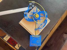
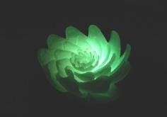
This is a 3D printed "Stick" version from the Ed Nieuwenhuys Fibonacci clock.
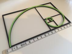
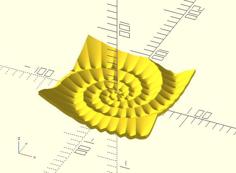
Fibonacci was an Italian mathematician who developed the series of numbers named after him. It was not a normal series of numbers, but one that also often occurs in natural processes. For example in sunflowers and shells. The sequence is simple. Each subsequent number in the series is the sum of the two previous ones: 1, 1, 2, 3, 5, 8,
But a clock? And what does Fibonacci have to do with Mondrian?
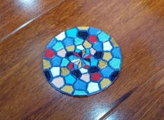
The colored areas separated by black lines are immediately reminiscent of Piet Mondriaan's paintings when the primary colors red, yellow and blue are used.
This clock uses colors and surfaces that follow the Fibonacci sequence.
Red + Blue = hours, (Yellow + Blue) x 5 = minutes. The stick above has 1 red + 2 blue areas = 3 o'clock In addition, 3 + 5 = 8 yellow areas + 2 blue areas = 8 + 2 = 10 areas of 5 minutes = 10 x 5 = 50 minutes. 1 + 2 = 3 hours, (8 + 2) x 5 = 50 minutes It is 3:50, ten to four.
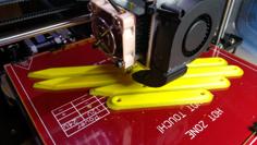
Designed with 3D printing in mind so almost no supports needed and 0.2 clearance between parts. Suitable for most printer tolerances.
A guide with electronic parts list, software and how to put it al together you can find on the website from the inventor:
https://ednieuw.home.xs4all.nl/Woordklok/FibonacciStick/Fibonaccistick.html
Or github for more:
https://github.com/ednieuw/fibonacci-Vierkantekokerklok
You need:
Designed with a minimum 30x30cm printbed in mind. Print the long parts in 2 half's diagonal. For smaler printbed's you have to cut the long prints to fit your printbed. User your slicer or other STL editor. I left the Mikey Mouse ears for extra bed adhesion, cut them off.
Please put the right site on the bed to minimize support.
Enjoy the result!
| Base_long_V4.stl | 531.7KB | |
| Base_short_V4.stl | 118.7KB | |
| Black_cover_V4.stl | 22.2KB | |
| glas_1_leds_V1.stl | 30.4KB | |
| glas_2_leds_V1.stl | 30.4KB | |
| Glas_3_leds_V2.stl | 39.7KB | |
| Glas_5_leds_V1.stl | 39.7KB | |
| Led_clip_V1.stl | 199.4KB | |
| Led_holder_Long_V4.stl | 760.6KB | |
| Led_holder_short_V4.stl | 190.1KB | |
| Top_long_V3.stl | 250.5KB | |
| Top_short_V4.stl | 79.6KB |