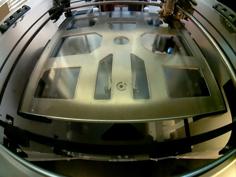
This is designed for the Meanwell PSU from the Ender 3 Pro.
Always wish you had CR-10 instead of the Ender 3? Put your Ender in an enclosure and need somewhere to put all the electric bits? Enjoy torturing your self and printer? Well friend then you have come to the right place. Now you can have All Electronics In One Unit.
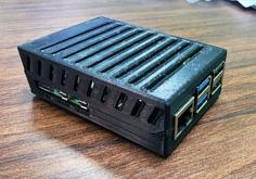
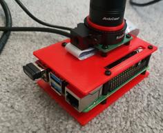
I looked for some time for an electronics enclosure that would do everything I wanted, hold an SKR Mini E3/Melzi, a Raspberry Pi, and some relays. Nothing seemed quite right. So, here it is, after weeks of learning Fusion 360, I have got to the point I feel like this is ready to share. Make no mistake, this is my first design, and it is not without problems. Print this at your own risk as I assume no responsibility for any damage to your printer or your mental state.
This is designed for the Meanwell PSU from the Ender 3 Pro.
Down to the nitty gritty. This was designed around the following parts.
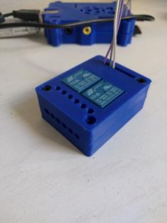
Relay module
https://www.amazon.com/gp/product/B072TR82K9
MOSFET module
https://www.amazon.com/gp/product/B077SBC1B5
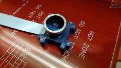
CSI to HDMI
https://www.amazon.com/gp/product/B06XDNBM63
Buck Convertors
Your favorite cheap blue buck converters
Secondary AC input
Any fused AC input such as https://www.amazon.com/gp/product/B01GBW8J8A
Your favorite 6025 fan or anything thinner.
Hardware required.
Outside
4 - M3x8 - Case
2 - M5x8 - Display - Reuse from original display
4 - M5 - Fan - No length requirment, or use fan screws
Top Level
4 - M2.5x5 - Buck converters
6 - M3x5 - MOSFET and Relay modules
4 - M3x8 - Layer mount - Kit
Bottom Level
5 - M3x5 - SKR Mini E3 - Reuse Melzi screws
4 - M2.5x5 - Raspberry Pi
3 - M4x5 - Layer mount - Reuse from factory PSU
1 - M4x8 - Display/Layer mount
All mounts are easily movable as they are separate bodies in the STEP files, if you would like to use different modules.
My personal setup is intended as such.
Relay for SKR/Melzi control
Relay for an enclosure heater
MOSFET for LED in enclosure
MOSFET for ventilation/cooling fan
Secondary AC input for heater power.
Everything else is pretty self explanatory.
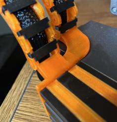
Assembly should be done from rear to front. The rear panel should slide onto the power supply, be careful will the terminals on the AC input, they should be able to slide in next to the terminals on the PSU with a little coaxing. The base layer should be attached to the PSU and all wiring completed and tested, and repeat for the second layer. The display mount should be added at this point too. Once you are happy with everything the case should slide over everything and a few M3 screws can be used to hold it in place.
No supports are required to print, however the case will most likely need a brim.
Please you caution with the screws holding the bottom layer to the PSU. The max depth for these is 3mm make sure your printed part is thick enough if not add a washer some spacer to prevent damage to the PSU.
| Bolts.txt | 467.0B | |
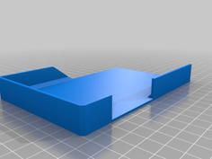
| Bottom_Layer-light.stl | 675.5KB | |
| Bottom_Layer.step | 293.8KB | |
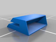
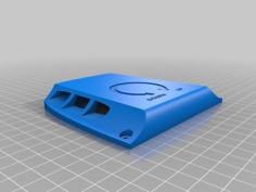
| Case.step | 157.6KB | |
| Case.stl | 116.0KB | |
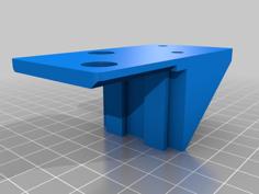
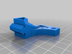
| Display_Mount.step | 37.6KB | |
| Display_Mount.stl | 72.1KB | |
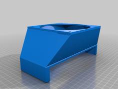
| Rear.stl | 408.4KB | |
| Rear_Parts.step | 281.5KB | |
| Top_Layer.step | 172.5KB | |
| Top_Layer.stl | 407.7KB | |
| Top_Layer_LED_Buck.stl | 338.8KB |