I needed a foot massager,
Parts needed, try ebay or amazon:
-two 20mm 5v motors with offset weights.
-L9110 motor controller
-attiny88 arduino, arduino nano or digispark
-arduino female/female and male/female wires **
-50mm 5v fan
-14awg speaker wire (for motors)
-soldering iron, paste, solder
-spare USB cord (remove the non USB A end)
-velcro straps?
** I recommend the 3 pack of mm, ff and mf as having some of each will help with other projects too. It's either that or solder everything.
Start by soldering the long single rows of pins to the arduino. (Unless you bought a presoldered one.) You don't need to solder on the 2x3 pins, we can use those later if they are unattached.
You can look up on google how to wire these boards together.
Basically:
VCC and VIN uses 5V/red on USB cable
GND is ground/black on USB cable
A-1a and B-1a pins to PWM pins on arduino
A-1b and B-1b pins can go to any digital pins on arduino
Wire Motors to green screw ins. A is one motor, B is the other.
Make sure to use the arduino PWM outputs for A1 and B1, or you will just get on and off motor control, no ramping. Every arduino version is different so you have to see where it is on your board. Change pin numbers in program to reflect pins you used.
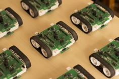
Arduino, fan and motor controller should all be connected to 5V and ground right from USB cord. I used the 2x3 header that came with the arduino, one row of 3 pins for 5v and the other row of three for gnd. Don't solder the2x3 on the arduino! Slide the jumpers over the longer pin side and then solder the USB cable on the other side, connecting all 3 of the pins for each voltage. Shown in photo, even if not clearly. You can also see in the photo the controller board is side-on and the arduino is flat, under the wires.
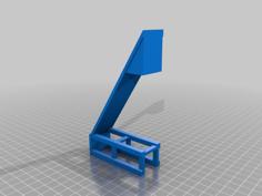
The v2 holders help the wires to the motor be supported, the spinning motor side is left open but the motors push far enough inside to be out of the way.. It can be covered with a cap, if needed too. If the motors rattle inside the casing, shim a ziptie in there or something. If you print them snug they'll be hard to remove if something goes wrong. ;)
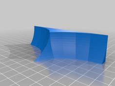
The two boards fit in the electronic cage, motor wires should go out the long slot. Fan should attach to lid and blow inward on electronics, For the motor; Black is GND and red is 5V. If you have a 3rd yellow wire on fan, it's not needed for this. Lid should friction fit on electronic cage. Fan may (or not) friction fit, shims or glue works too.
There's a power cable loop on lid. Ziptie the cables on either side to prevent cable being pulled out easily.
If all went well, you should now be the proud owner of a strap on vibrator.. congrats. Sorry I meant foot massager.
| 5v_motor_cage.stl | 49.6KB | |
| 5v_motor_cage_V2.stl | 58.0KB | |
| 5v_motor_electronic_cage.stl | 13.6KB | |
| 5v_motor_electronic_lid.stl | 16.6KB |