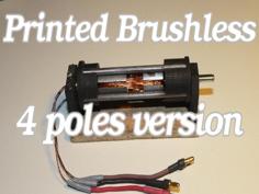
I hate using unnecessary wires.The other sensors use 3- 6 additional wires to connect routed to the ramps/MKS board.An inductive sensor is heavy and cable is big and heavy too.So in order to avoid that I designed a DIY Touch-MI Z-probe for auto-leveling a 3d printer without wires.
Description:
The signal from an optic probe(DIY touch-Mi) is sent wire less via an infrared light (IR diode) to an infrared sensor connected to a 3D Marlin board on the z-end switch connector.
The power for Z-probe and IR led is coming from 12V power supply of the hotend fan.
Materials:
Note:
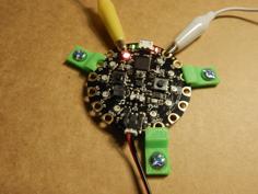
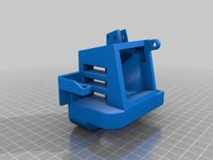
- The MOSFET transistor along with resistors are soldered on the same board as the IR led (green perf board).On the buck converter I soldered on the IN pins a JST PH 2.0 connector.
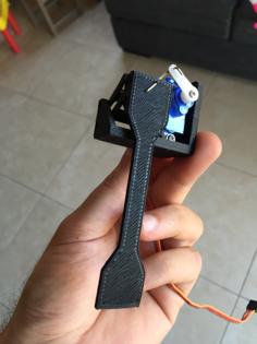
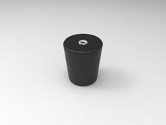
The magnetic module activation(12mm dia magnet) if installed with double side sticky tape on the x carriage in the left.
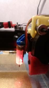
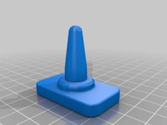
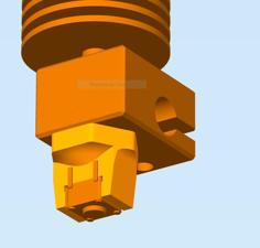
Make sure the DIY touch me sensor is installed vertically.Use a spirit level to ensure that. - added version 3 of touch-mi sensor.It looks better.
- Attention:The magnet from the module activator to be adjusted back enough to avoid being triggered during printing session.It will activate the probe only when homing the printer head.
- The probe will be adjusted in close position 2mm above the hot-end nozzle.You can use some 2 mm thick printed sheet for calibration.
- The probe can be used also as stand alone DIY touch -mi probe routing the wires to MKS board Z end stop connector.
- In place of the screw in can be used an 2.5 mm broken black drill bit, and sharpen the tip(pointed tip).For stopper if can be used a 3 printed or metallic washer and glued on the drill bit.
Todo:
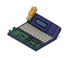
Design a new pcb to for all electronic parts(IR-TX) and attached at the back of the sensor.
The wireless part can be adapted also to BLTouch
inductive sensor and others.
Marlin firmware changes.
//#define BLTOUCH // ANTClabs BLTouch sensor (might also work with clones)
//#define SN04 // Green sensor
define INDUCTIVE_NO // Normally open inductive sensor
//#define INDUCTIVE_NC // Normally closed inductive sensor
//#define SERVO_PROBE // Endstop switch on rotating arm. Set servo angles!
//#define NOZZLE_PROBE // Nozzle wired up to contact metal on bed
//#define TRIPOINT
//#define LINEAR
define BILINEAR
//#define UBL
//#define MANUAL
define SENSOR_LEFT 49//(use your value here )
; add in your slicer G-code
;Start G-code
;add after G28
G29
G1 Z-5.0 ;this is to retract the sensor probe(magnet) assuming the Z_HOMING_HEIGHT is 5mm
G1 Z5.0;go back
https://youtu.be/1siBJUK0WSE
https://youtu.be/zdy2BfiY3-g
Tested accuracy of the sensor.
M48 Z-Probe Repeatability Test
Finished!
Mean: -0.006800 Min: -0.010 Max: -0.003 Range: 0.008
Standard Deviation: 0.002337