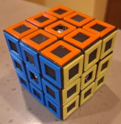
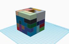
The Lament configuration - art by artist064 "The original Lament Configuration was created by Simon Sayce for the original Hellraiser movie". I have attempted to remain faithful to the original design, however it is apparent that multiple on-screen props were used with differing configurations, even some faces mirrored. To this end I have settled on the widely used HR1 configuration by Xane.
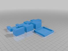
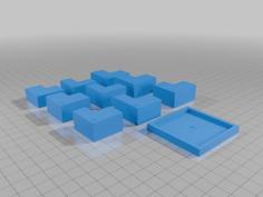
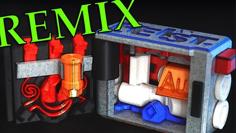
The previous print-in-place design was quite an ambitious 36 hour print, sensitive to clearances and elephant's foot. It was a lot to ask for an all or nothing chance at success. This version is designed to be printed in separate components and assembled. The aim is to produce a version suitable for SLA printing in separate pieces, though this one is still for FDM. Print at 0.2mm layer height (less important now, only really applies to the core or not at all for the alternate core).
Older video explaining mechanism Will put together an assembly video soon, but it's pretty self explanatory and reversible (see pictures). Some action shots.
Note: Parts are in assembled position, not the ideal printed layout. I would suggest flipping the "upper" shell over. For the dials, I prefer a small support disk by enabling support interface at 100% or just print internal side down. Following over-extrusion, "Z" seams are most likely to cause binding issues with moving parts. Random Z Seam Alignment may help.
The photos form kind of an assembly sequence but could use some explanation. There's your first puzzle. Updated assembly video and a rather nice example by Igor Sedykh.
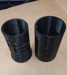
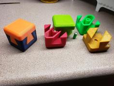
Firstly the dials are inserted into each of the outer shells, and retaining rings press fit to keep them in place but turning freely. Some light sanding or scraping might be required to take off any sharp or squished edges for a good fit. Mine have come loose from repeated disassembly - a couple of drops of glue might help.
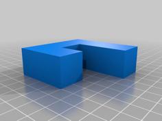
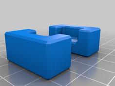
Next the internal sliding cylinder is fitted over the "bottom" (larger) maze and manipulated to the start of the maze until it sits flush as shown. Note orientation of the small outer fins towards the "bottom".
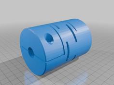
Now the core goes in, careful of orientation with the spinning fins towards the "top" or smaller maze half. Insert with fins aligned to the gap until the halfway point where they also align with the notch which allows them to be rotated in place and captured inside the internal tracks.
The trick for inserting the core into the second half (which I don't have a photo for) is to pull it out so half protrudes, turn to align the protruding fins with "fingers" of the first half so they can both be inserted into the gaps of the second half until again the fins are aligned with the halfway notch and can be rotated into position inside the corresponding internal tracks.
Now the whole puzzle can be closed, rotating the "top" dial until it closes completely. Further rotating the "top" dial 180 degrees allows the bottom dial to turn, engaging the locking mechanism.
For the (optional) spring, I have found 5mm OD x 120mm compression spring to be a good size. It doesn't open the box completely, but allows for a length of bamboo skewer or similar to keep it straight long enough to close the box. Longer springs will bow outwards when compressed and need some kind of telescoping structure to keep them centred before the box closes around it.
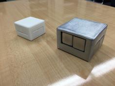
As for finishing, it is designed for painting and sanding back to reveal detail. I'm thinking instead of paint I will try some kind of low shrinkage resin with pigment powder to fill the low spots. This should allow for a polished flat surface completely hiding any layer lines.
Update 02/06/2022: Included embossed version using updated art cube (thicker top/bottom details for 0.4mm nozzle) as well as print in place dial option (the retaining rings are more hassle than they are worth if you can manage the clearance). It is easier to print thin gaps than thin walls but over-extrusion will fill in the fine detail - try submerging below the build plate to test the top surface finish before committing to a full print.
All the fiddly bits on the top few layers seem to be quite susceptible to over-extrusion. I found best results from dialing back flow rate to the point of causing under-extrusion elsewhere (75%). There are a lot of retractions so settings like ‘Retraction extra prime amount’ will also add unwanted material. A trick to getting this right in Cura is to add a support blocker cube positioned over the top few layers and change it to ‘Modify settings for overlaps’. This allows the flow rate to be tweaked only for the detailed layers as described here.
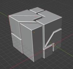
Update 4/10/2022 (v4.2): Noticed some missing detail in the artwork used. Extended spring guide and limit rotation to prevent false locks (force 180 degree turn before engaging maze).
Looks like a copy has found it's way to Chris Ramsay's desk. Seems to be a remodel but looks like all the pieces are there. I don't think he realized it was already solved!
| altcore_extra_clearance.stl | 339.9KB | |
| core_alternate.stl | 330.2KB | |
| core_extra_clearance.stl | 248.1KB | |
| core_split.stl | 227.4KB | |
| core_split_spinner1.stl | 57.5KB | |
| core_split_spinner2.stl | 57.5KB | |
| lower-art-v4.2.stl | 3.2MB | |
| lower-art-v4.2e.stl | 3.2MB | |
| lower-art-v4.2es.stl | 3.0MB | |
| lower-art-v4.2s.stl | 3.0MB | |
| lower-dial-v4.2es.stl | 256.2KB | |
| lower-dial-v4.2s.stl | 267.5KB | |
| lower-mmu-v4.2.stl | 3.3MB | |
| lower-v4.2.stl | 1.2MB | |
| lower-v4.2s.stl | 138.0KB | |
| Puzzle_Cube_v4.2.scad | 23.5KB | |
| Puzzle_Cube_v4_core.stl | 263.0KB | |
| Puzzle_Cube_v4_slider.stl | 93.8KB | |
| retaining-ring.stl | 65.7KB | |
| stand.stl | 1.3MB | |
| stand_repaired.stl | 1.0MB | |
| upper-art-v4.2.stl | 3.2MB | |
| upper-art-v4.2e.stl | 3.2MB | |
| upper-art-v4.2es.stl | 2.9MB | |
| upper-art-v4.2s.stl | 2.9MB | |
| upper-dial-v4.2es.stl | 288.0KB | |
| upper-dial-v4.2s.stl | 287.5KB | |
| upper-mmu-v4.2.stl | 3.3MB | |
| upper-v4.2.stl | 1.0MB | |
| upper-v4.2s.stl | 132.9KB |