Deadbolt Combination Lock 3D Printer Model
The file 'Deadbolt Combination Lock 3D Printer Model' is (stl) file type, size is 3.2MB.
The file 'Deadbolt Combination Lock 3D Printer Model' is (stl) file type, size is 3.2MB.
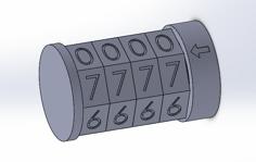
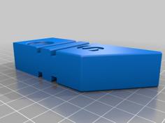
This is a combined combination lock and a deadbolt.
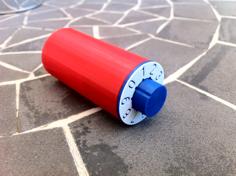
The three cylinders rotate smoothly on simple gear bearings; with 1 of 17,576 possible unlock combinations. Once unlocked, the lock slides out of the bolt-keep.
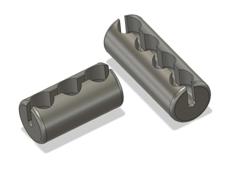
Crack-resistant - Each cylinder has 25 blind partial (false) lock pin channels, and one blind full (true) lock pin channel. All cylinders must align to the correct combination to fully pass the lock pin.
Mount the lock (left side, or right side) on a door that opens-in, or opens-out. Two versions of a Bolt Keep are provided: one model that mounts on a plane that is parallel to the door, and another model that mounts perpendicular to the door plane (e.g. on a door jamb that faces the lock).
• The lock has three sliding positions: Locked, Open (middle position), and Remove. The cylinders may be randomly rotated while in any of these positions to hide the unlock combination.
• Set the cylinders to the unlock combination to allow the lock to slide from the Locked to the Open position (or Open to Locked position). Rotate the cylinders randomly to prevent the lock from sliding into the Locked or Open position.
• Set the cylinders to the unlock combination, then rotate all cylinders 180 degrees, to allow the lock to slide from the Open to the Remove position. Slide the lock fully away from Bolt Keep, until the lock may be lifted from the door mounting plate.
• Printable on a 120mm build plate.
• Assembled dimensions of the lock (not including the Bolt Keep): 4.9cm (thick), 15.4cm (length), 9cm (wide).
• The Door Plate and Bolt Keep are intended to be installed on the same plane. For installations where the surfaces of the door and door jamb are not on the same plane, separate adjustable mounting spacer models are provided for the Door Plate and for the Bolt Keep. There are two “flat” spacer models, one for each of the Bolt Keep and the Door Plate. There is a third “angled” spacer for the Bolt Keep, which is intended to be used in situations where there is door molding with an angled surface. All spacers are supplied at 1mm thick. Use a Slicer to apply the needed scaling in the Z axis to print the desired spacer thickness that will provide the offset necessary to position the Door Plate and the Bolt Keep on the same plane.
Mounting hardware:
All parts print at 0.2mm line height, with 50% infill.
Supports are NOT required, except for two parts. These parts require supports: CylinderOuter_Indicator, and CylinderMiddle_Indicator.
Print all parts in the orientation as supplied in their respective models.
Small Gear (x 12)
Gear Spacer Plate (x 2)
Gear Frame (x 1)
Cylinder Outer, Part A (x 1)
Cylinder Outer Indicator Ring (x 1)
Cylinder Middle, Part A (x 1)
Cylinder Middle, Part B (x 1)
Cylinder Middle Indicator Ring (x 1)
Cylinder Inner, Part A (x 1)
Cylinder Inner, Part B (x 1)
Cylinder Inner Indicator Ring (x 1)
Cap (x 1)
Door Plate (x 1)
Case (x 1)
Case Top (x 1)
Bolt (x 1)
Bolt Keep (or Bolt Keep 90) (x 1)
Door Plate Spacer (optional)
Bolt Keep Spacer (optional)
Bolt Keep Angled Spacer (optional)
| Lock-Bolt.stl | 11.8KB | |
| Lock-BoltKeep.stl | 68.1KB | |
| Lock-BoltKeep90.stl | 58.7KB | |
| Lock-BoltKeepSpacer.stl | 14.7KB | |
| Lock-BoltKeepSpacer_angled.stl | 14.2KB | |
| Lock-Cap.stl | 488.6KB | |
| Lock-Case.stl | 874.8KB | |
| Lock-CaseTop.stl | 821.6KB | |
| Lock-CylinderInner_A.stl | 382.5KB | |
| Lock-CylinderInner_B.stl | 712.8KB | |
| lock-CylinderInner_Ind.stl | 847.6KB | |
| Lock-CylinderMid_A.stl | 485.2KB | |
| Lock-CylinderMid_B.stl | 687.4KB | |
| lock-CylinderMid_Ind.stl | 877.2KB | |
| Lock-CylinderOuter_A.stl | 628.0KB | |
| Lock-CylinderOuter_Ind.stl | 967.8KB | |
| Lock-DoorPlate.stl | 122.9KB | |
| Lock-DoorPlateSpacer.stl | 81.7KB | |
| Lock-GearFrame.stl | 500.9KB | |
| Lock-GearSpacerPlate.stl | 375.9KB | |
| Lock-SmallGear.stl | 245.0KB |