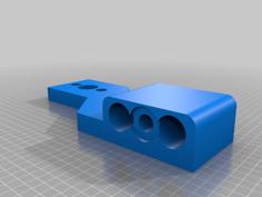
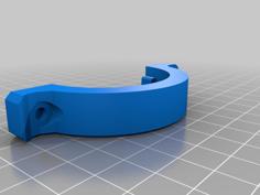
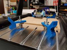
I just printed the model with LM16UU bearings and noticed the carriage does not fit with the default "side plates", so I made my own (out of aluminium)
The flex that those 16mm bars have is still quite a bit, so I guess if you really want a sturdy machine you might have a better time using completely different linear guides.
I will add a LM12UU and LM14UU variant for the X linear guides soon.
I recreated the model using the (free) OpenSCAD (http://www.openscad.org) modeler.
This new model incorporates some improvements that I felt were necessary after printing the original design that I made in Fusion 360.
I re-exported the STL files from the OpenSCAD file and made a LM10UU and LM16UU version for the X carriage, and a LM8UU and LM10UU version for the Z carriage.
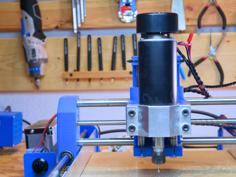
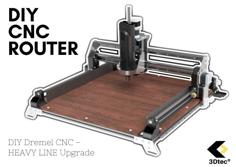
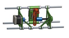
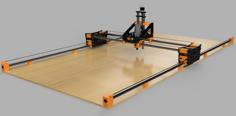
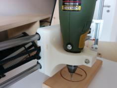
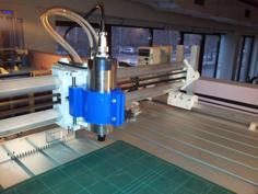
I wanted a more sturdy Z-Axis for the 3018 Pro so I designed a better one.
The main problems with the original design are the cheap LM8UU and LM10UU bearings and bad quality T8 spindles, I also found the 2x 10mm linear guides for the X axis will bend easily, all of this together gives the machine a lot of play by default, making cutting harder materials very slow.
I printed the parts on my Ender 3, but had to make the holes in the design a bit bigger to make all parts fit correctly, so WATCH OUT, the STL's that are uploaded have +0.5mm on the vertical holes and +0.4mm on the horizontal ones!
If you can print your holes perfect, go set the VerticalHoleDiameterAdjust and HorizontalHoleDiameterAdjust "variables" / "parameters" to 0 in the OpenSCAD drawing and export new STL files.
I used PLA with 20% infill and a 2.5mm wall thickness.
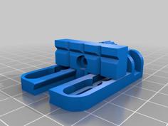
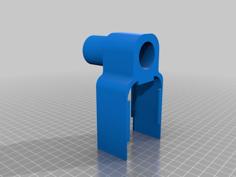
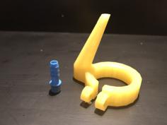
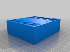
I designed the Spindle mount separate from the Z Carriage so it can be replaced with other kinds of mounts.
These parts are needed for all variants of this modification
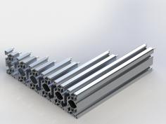
These parts are ONLY needed if you want to upgrade the X axis linear guides to 16mm bars
These parts are needed if you only want to upgrade the X axis's bearings and spindle
These parts are ONLY needed if you want to upgrade the Z axis linear guides to 10mm bars
These parts are needed if you only want to upgrade the Z axis's bearings and spindle
Happy to answer any questions!
| CNC3018ZAxis.scad | 16.4KB | |
| SpindleMount.stl | 1009.3KB | |
| XCarriageLM10UU.stl | 2.3MB | |
| XCarriageLM16UU_recommended.stl | 2.3MB | |
| YCarriage.stl | 940.3KB | |
| ZCarriageLM10UU_recommended.stl | 1.9MB | |
| ZCarriageLM8UU.stl | 1.9MB |