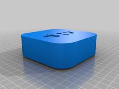
This is a customizable box for breadboards. I draw it in FreeCAD and parametrized the most important dimensions in a spreadsheet, so that it is easily adaptable for different board sizes.
I developed this design for different sensor and controller boxes, that I use in my home automatization. For example an Node-MCU board or Node D1-mini on a breadboard for measureing environmental parameters or to controll the heating system. Therefore I included an opening for a USB-connection (mini-USB, positioning parametrized).
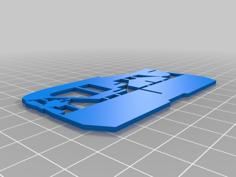
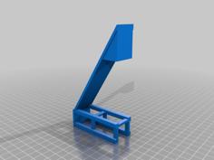
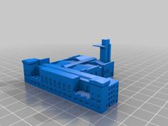
This design can be easily modified for further openings for sensors (e.g. breakout boards or environmental sensors) or other connectors (e.g. RS232 connector) - Two examples see pictures attached.
The parameters are set in the FreeCAD file on the spreadsheet "Parameters". The green encircled parameters are the input parameters to be modified. The yellow circled parameters are calculated auxilary parameters,needed for the details of the drawing (DO NOT MODIFY or DELETE!)
| Bottom_Example.stl | 110.6KB | |
| Customizable_Breadboard_Box_Bottom.FCStd | 122.3KB | |
| Top_Example.stl | 158.5KB |