Bike Dynamo Rear Light & USB Charger 3D Printer Model
The file 'Bike Dynamo Rear Light & USB Charger 3D Printer Model' is (stl) file type, size is 412.2KB.
The file 'Bike Dynamo Rear Light & USB Charger 3D Printer Model' is (stl) file type, size is 412.2KB.
This device is a simplified AC to DC converter using a capacitor and rectifier, regulated to 5V, to power a rear LED or charge a battery pack for headlights or your phone. The 12V dynamo generates power, which is converted from AC to DC by the bridge rectifier. The capacitor stabilizes the voltage, and the voltage regulator limits it to 5V. A toggle switch diverts the power to either the rear LED or the USB port for charging.
I created this simple dynamo power supply during COVID when my friends and I would go out for cycles. This design is very minimalist, and the electronics are arranged in a 3D structure, which was an interesting experience to solder. For the fun of it, I also decided to include a missile-launch switch cover for the power diversion switch.
With this setup, you can either power the rear LED or use the USB port to charge a battery pack for your front LEDs and phone.
Rectifier Connection:
Capacitor Connection:
Voltage Regulator Connection:
Toggle Switch Connection:
USB Port and LED Connection:
Ensure all connections are secure and check polarity before powering the system.
This setup will allow you to switch between powering the rear LED light and charging via USB.
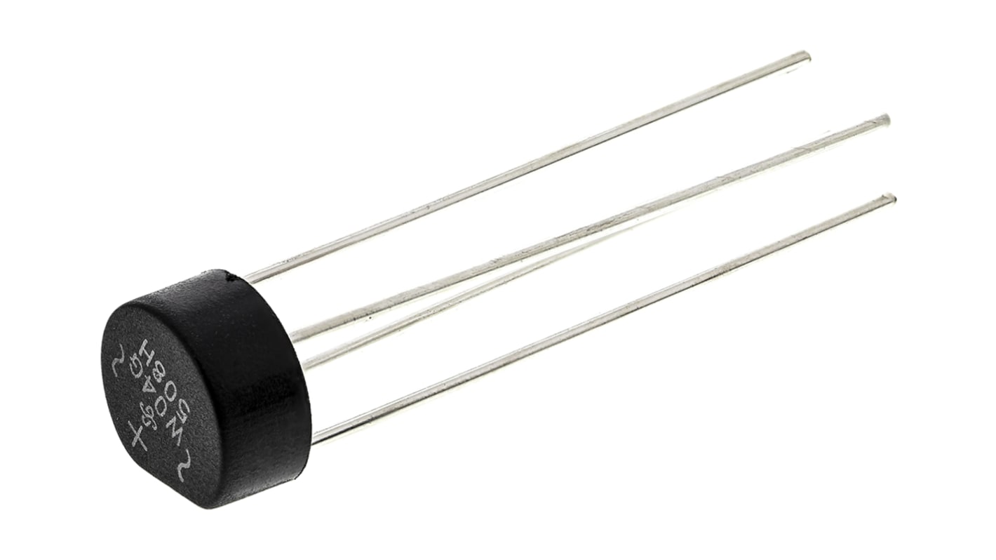
1.5A 400V Bridge Rectifier
Converts AC to DC.

1000µF 35V Radial-Lead Electrolytic Capacitor
Stabilizes voltage.
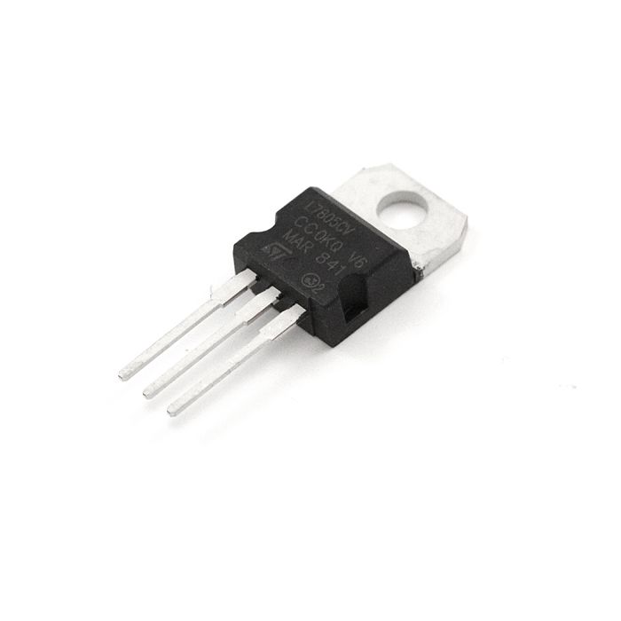
3 Pin +5V 1A Fixed-Voltage Regulator
Provides consistent 5V output.

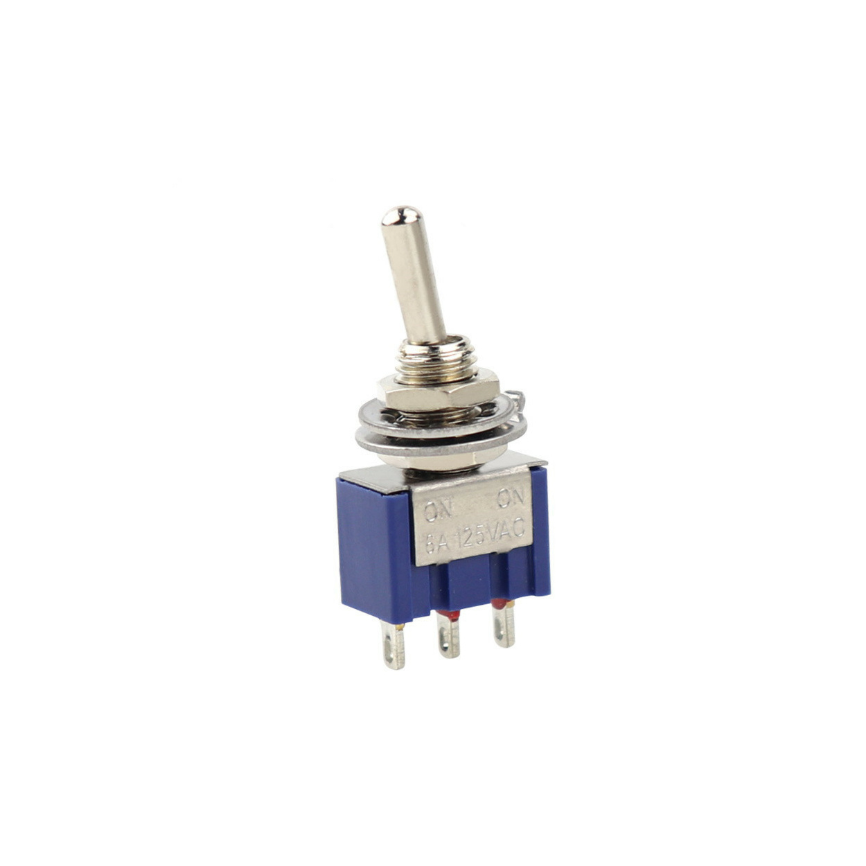
3 State Toggle Switch
Switches between powering the rear LED light and USB output.

USB 2.0 Port
For charging power bank.

±m5 Torsion Spring


| left_case.stl | 597.9KB | |
| right_case.stl | 586.9KB | |
| switch_cover.stl | 104.6KB |