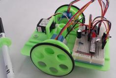
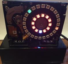
Hello there, fellow film photographers! As you know, film photography equipment does wear out over time, and the most common part that wears out is the photographic shutter. It's important to check the performance of the shutter when buying a used camera or when evaluating existing cameras. Recently, I came across an article online about a device based on Arduino Nano that can measure the shutter speed of film cameras. The article is available here: [https://projecthub.arduino.cc/hiroshootsfilm/shutter-speed-tester-for-film-cameras-8ffb04]. I repeated the circuit on a breadboard and immediately began thinking about the potential use for this device, as it is not very convenient to use a breadboard. I used a Chinese clone of the Arduino Nano 3.0 with an Atmega328 chip.
As the power source, I chose a 6F22 9V battery. The voltage from this battery, through the 6F22 connector and an SS12D00G3 switch, is supplied to the VIN pin. Other devices are powered by the 5V pin. With a typical 6F22 battery with a capacity of 500 mAh, this allows the device to run for 24 hours, given that the electrical current drawn by the board is only 20 mA.
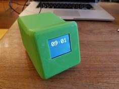
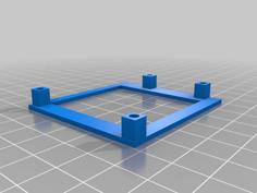
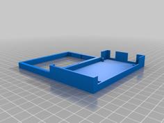
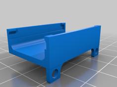
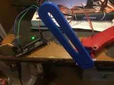
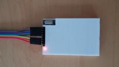
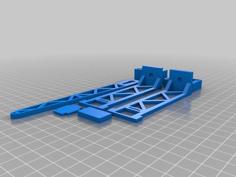
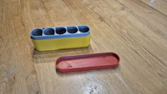
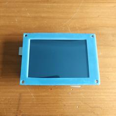
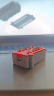
Otherwise, the circuit is similar to the one described in the article above. The case consists of seven printed parts, four of which are flat. The Arduino Nano board and OLED screen are placed in special recesses, like a sandwich, stacked on top of each other, with a plexiglass sheet (28x20x2) protecting the screen from damage, and a printed plastic spring clamping the battery. After final assembly, a protective cap is screwed onto the phototransistor using two small screws. All electrical connections are made using thin wires. The housing is assembled after final soldering, allowing you to choose optimal wire lengths and check circuit operation before final assembly. Using my case eliminates the need for a printed circuit board. All you need is a 3D printer, electronic components, thin wires, and a soldering iron to assemble the case. As an upgrade to the circuit, you could add a reset button. It could be placed below the LCD screen, although I prefer a more minimalist approach. While you are adjusting the shutter and changing the shutter speed, the device will automatically be prepared for new measurements.
Here's what you'll need:
-Arduino Nano 3.0 Atmega328
-0.96" OLED Display 128 x 64 SSD1306 I2C
-Phototransistor NJL7502L
-Resistor 10k ohm
-2.2x6.5 ISO 7050 (DIN 7982) 2 pieces
-2.2x19 ISO 7050 (DIN 7982) 8 pieces
-SS12D00G3 switch, 2-position, SPDT 1P2T, 3-pin-
-Battery 6F22 9V
-Connector 6F22
-Plexiglass 28x20x2
-Thin colored wires.
I will be glad to hear your feedback!
Update 05/14/2024.
After completing the initial version of the shutter speed testing device, I came across an interesting article on the internet. The link to the article is: https://lead-pepelats.ru/blog/device-for-checking-value-of-camera-shutter-speed/ . In this article, the author improved the original design and software by adding a button for resetting measurement readings and increasing the accuracy of the device for measuring very short exposure times. Instead of connecting the sensor to an analog pin, he connected it to a D3 pin, which supports hardware interrupts. I highly recommend reading the article and the author's blog.
Let's return to the project.
I modified the design of the 4_Button_case and 5_Plexiglass_case parts to be able to install a 6x6x5mm 2PIN push-button switch that will reset the measurement readings. If you are going to make a circuit with a reset button, download versions 4.1 and 5.2. I also strengthened the upper part of the battery case so that the upper edges do not bend, see model 1.1_Battery_case, it is completely interchangeable with the old version. I also made an alternative mounting option for the phototransistor nozzle. I replaced the screws 2.2x6.5 ISO 7050 (DIN 7982) with a plastic thread, so the phototransistor housing protects it and also tightens the two halves. The new files are 2.1_Arduino_case; 3.1_Screen_case and 6.1_Phototransistor_cover.
| 1.1_Battery_case.stl | 7.1MB | |
| 1_Battery_case.stl | 4.9MB | |
| 2.1_Arduino_case.stl | 1.9MB | |
| 2_Arduino_case.stl | 1.9MB | |
| 3.1_Screen_case.stl | 396.5KB | |
| 3_Screen_case.stl | 325.6KB | |
| 4.1_Button_case.stl | 298.0KB | |
| 4_Button_case.stl | 270.6KB | |
| 5.1_Plexiglass_case.stl | 213.9KB | |
| 5_Plexiglass_case.stl | 186.4KB | |
| 6.1_Phototransistor_cover.stl | 1.4MB | |
| 6_Phototransistor_cover.stl | 2.9MB | |
| 7_Spring.stl | 83.9KB |