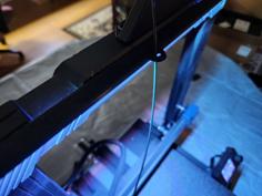
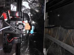
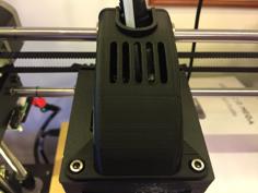
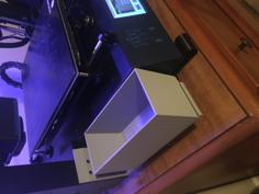
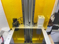
This is a z axis stabilizer for my Anycubic i3
We will need:
Studs M8 500 mm - 2 pieces
Nuts M8 - 8 pieces
M4 nuts - 8 pieces
Screw M4/15 mm - 8 pieces
M3/15mm screw - 4 pieces
The order of assembly:
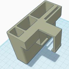
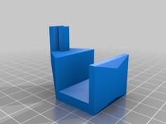
1) Screw the lower "1 Lower Right.stl" to the printer housing with M4 screws into the extreme holes in the printer housing.
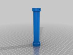
2) Assemble the tensioner.
2-1) In "1 Lower Right.stl", insert the M8 nut into the nut hole and tighten the 500 mm diameter stud so that it protrudes 8 mm from the bottom. !!! And pull out the stud with the nut from "1 Lower Right.stl".
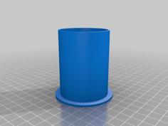
2-2) Put "3-4 Lower Tensioner.stl" on top. Then put the "5-6 Upper Tensioner.stl" on the stud and screw it on top with the M8 nut. Turn the "5-6 Upper Tensioner.stl" with your hand clockwise until it stops rotating freely.
3) Put the part "7 Upper Right.stl" on the assembled stud and fasten it with the M8 nut. Scrolling the part "7 Upper Right.stl" clockwise until it stops.
4) On the printer at the top, unscrew the 2 M3 screws that secure the guide along the Z axis.
5) Insert the assembled rod with the upper mount into the part "1 Lower Right.stl" which is screwed to the base of the printer, secure the lower part with the M8 nut. Tighten. Put on the lower and upper caps.
6) Screw the upper part with M3 screws.
7) Repeat all operations with the "left side".
Нам понадобится:
Шпильки M8 500 мм - 2 штуки
Гайки М8 - 8 штук
Гайки М4 - 8 штук
Винт M4/15 мм - 8 штук
Винт M3/15 мм - 4 штуки
Порядок сборки:
1) Прикрутите нижнее крепление "1 Lower Right.stl" к корпусу принтера винтами M4 в крайние отверстия в корпусе принтера.
2) Собираем натяжитель.
2-1) В "1 Lower Right.stl" которую прикрутили к принтеру вставьте гайку M8 в отверстие для гайки и закрутите шпильку диаметром 500 мм так, чтобы она выступала на 8 мм снизу. !!! И вытаскиваем шпильку с гайкой из "1 Lower Right.stl".
2-2) Сверху надеваем "3-4 Lower Tensioner.stl". Затем надеваем "5-6 Upper Tensioner.stl" на шпильку и завинчиваем ее сверху гайкой M8. Крутим "5-6 Upper Tensioner.stl" рукой по часовой стрелке пока он не перестанет свободно вращаться.
3) Надеваем на собранную шпильку/натяжитель деталь "7 Upper Right.stl" и закрепляем ее гайкой M8. Прокручивая деталь "7 Upper Right.stl" по часовой стрелке до упора.
4) На принтере вверху открутите 2 винта М3, которыми крепится направляющая вдоль оси Z.
5) Вставьте собранный стержень с верхним креплением в деталь "1 Lower Right.stl" которая прикручена к основанию принтера, закрепите нижнюю часть гайкой M8. Затянуть. Наденьте колпачки нижний и верхний.
6) Прикрутите верхнюю деталь винтами М3.
7) Повторите все операции с "левой стороной".
| 10_cap_on_the_upper_tensioner_-_2_pieces.stl | 44.5KB | |
| 12_cap_on_the_nut_M8_down_-_2_pieces.stl | 802.4KB | |
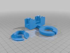
| 1_Lower_Right.stl | 412.5KB | |
| 2_Lower_Left.stl | 412.5KB | |
| 4_Lower_Tensioner.stl | 50.5KB | |
| 6_Upper_Tensioner.stl | 1.1MB | |
| 7_Upper_Right.stl | 351.4KB | |
| 8_Upper_Left.stl | 351.4KB | |
| All_the_details_are_on_the_platform.stl | 5.4MB |