Anet A6 Y-Axis Cable Chain 3D Printer Model
The file 'Anet A6 Y-Axis Cable Chain 3D Printer Model' is (stl) file type, size is 162.8KB.
The file 'Anet A6 Y-Axis Cable Chain 3D Printer Model' is (stl) file type, size is 162.8KB.
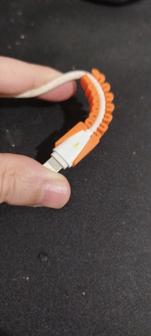
Here is a Y-Axis Cable Chain for an Anet A6 printer. I was unable to find one on Thingiverse so I took it upon myself to Remix RotoScan generic chain.
Demonstration link: https://youtu.be/PpistVXVouQ
I was printing a Thing about a week and a half ago when I heard an awful noise coming from my printer. My Y-Axis cable had become pinched between the bed leveling screw and the guide rods of the bed, halting the bed movement and torquing my wiring. Even before this had happened, I heard the occasional "pop" of the plastic coil cable wrapping becoming caught on the acrylic, so this problem was solved, as well. Fortunately, the wiring did not pull loose from the heated bed connectors and my stepper motor seems undamaged (so far). And that's the story of how this Remix was born.
I understand I may receive concerns about straining the heated bed wiring connector, but after several days and many prints of testing, I have not had one problem with it. I can physically observe the tension and torque moment on the plug by the chain and if there is any pressure there it is small enough that I cannot see or feel it. If you follow my post-printing notes you should be perfectly fine.
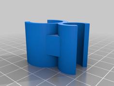
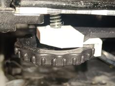
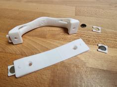
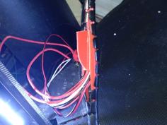
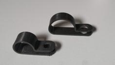
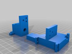
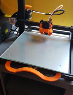
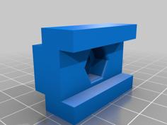
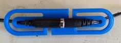
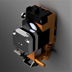
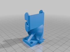
The chain links remained the same as RotoScan had originally designed, but the end connectors were heavily modified for the A6 architecture. The chain connector that is attached to the frame is held in place with the top screw that mounts the Y-Axis stepper to the acrylic, as can be seen in the photos. The chain connector that is attached to the bed simply slips over the wiring connector and uses its flexible tab to lock in place.
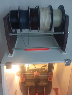
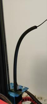
I am currently using 28 chain links (not including the end connectors, so 30 pieces in all) on my printer. You could probably get by with 20 links, but a longer chain means less stress on the wiring and plugs. 28 links leaves about 8 inches of wire coming out from under the mainboard after rerouting, which is plenty to be able to plug in. The wiring was rerouted through the back of the acrylic, under the stepper motor, and through the hole in the side acrylic located under the mainboard, as seen in the pictures.
A Few IMPORTANT Notes
You will need to remove the little green plug on the ends of the heated bed power cables to thread the wires through the chain. This can be replaced after installation, just note which wires go in which position (red in the left and black in the right if I recall). I found it was easier to thread and less damaging to the exposed wire if I bound the two cables together with a bit of electrical tape around the ends. The thermistor connector will slide through just fine. Before assembling the chain, I suggest filing/sanding the outer facing tabs of the links (the ones with the indentations) a little bit to smooth the layers and ensure a fluid swivel when connected to other links. Also, smooth out the inside rim and flats of the indentations. The easier the chain can flow, the less stress on your bed wiring connector. IF YOU SAND/FILE AND ASSEMBLE THE CHAIN PROPERLY THE TWO LEVELS OF CHAIN SHOULD REMAIN ALMOST PERFECTLY PARALLEL TO THE HORIZONTAL WHEN PRINTING/MOVING THE BED. This is very important for minimizing the stress and torque on the heated bed plug.
| A6CableChainEnds.stl | 118.5KB | |
| CableChain.stl | 321.7KB | |
| CableChainx4.stl | 1.3MB |