I made this model last year and it worked reliably for quite a few months and now I decided to publish the design. I'm sure some other people may benefit from it.
Warning: this is not a very simple project to complete, so please be advised that some basic electronics skills are needed (might be acquired along the way, no soldering required). Please exercise patience and curiosity. I sincerely hope you'll like it.
Well, the most important reason is that I have two wonderful cats, and during the period of heating in the winter the air becomes just too dry (<20%) and the cats start collecting static electricity in their fur, which makes cuddling painful for them and for me.
I also don't like super dry air from a health perspective, my mouth and nose are getting too dry and it's just not a pleasant feeling. I prefer relative humidity of 40-60%.
The reason why I was frustrated with the off-the-shelf air humidifiers is two-fold:
I'm considering printing another one for this winter season, I liked the result.
First of all, you will need some engineering skills to make sure the stepper rotates with the right speed, I'll explain why I chose the parts I did, but I won't elaborate on how to actually make it work, you can use countless Youtube videos to work it out for yourself. What you are looking for is a steady rotation of a stepper so that evaporating disks make one full rotation per minute. That should be more than enough.
Second, apart from the printed parts, you'll need some gear:
As for plastic, roughly you might need 1 kg of filament per section. There is A LOT of 3d-printing to do. You may experiment with colors as well. I recommend PETG. There's no specific requirement for the plastic other than it should be safe and not degrade from the constant contact with water.
Layer height should be 0.2 (with a 0.4 nozzle). It's enough to have 15% infill for most parts, see comments below, int he Assembly section.
Okay, here is just what I used, you should consider your options based on the availability of the parts.
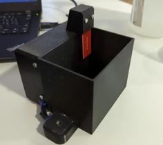
So I used NEMA17 stepper with a TMC2209 driver, controlled by a ESP32 microcontroller. I used Esphome project to program the microcontroller.
The sole purpose of the setup is to make sure that the motor rotates with the constant speed, so that's rather simple. The choice of TMC2209 is dictated by the silent operation of the stepper that results from using it, as it does a very clever microstepping even in the simplest of the scenarios etc.
It is advisable to have a gradual acceleration during the motor start to reduce mechanical stress on the gears and section connectors.
But again, consult Youtube or other resources for more info.
When choosing dimensions for the container, please remember that it needs to cover only a half of the height of the model. So it might be 150 millimeters in height or taller. Remember that the larger the bottom area of the container, the less frequent water top-ups are needed. I use 50(w)x30(l)x25(h) container and it works well for me. I need to top it up once every two or three days. If you have the container that fits the model height, you may use it as a summer storage.
I recommend transparent plastic, it's a lot easier to pour water and the check the water level visually this way.
After a season of use, there will be heave scale on the bottom and the sides of the container. I use just a concentrated lemon acid to clean it up, same applies to evaporating disks and legs and joints of the model, just pour a generous doze of crystallised lemon acid (it's rather cheap) into the hot water (50-60 Celsius), Leave it rotating for half an hour, that should be enough for a complete descaling.
The model is designed for layer height: 0.2
Infill: 50+% for the legs, gears, section connectors (via the bearing), 15% for the rest
You may use a Fusion model or a large STL file to understand how parts fir together.
First you need to print and assemble the gear block
Secure the gear holder to the leg using 4 m3x10 bolts. You won't be able to do it once you insert the smaller gear into place.
Put a bearing into the gear holder, insert a shorter end of the smaller gear into it, then secure the smaller gear with the NEMA17 rotating rod on the other side, secure the motor to the gear holder with 4 m3x10 bolts.
Assemble the larger gear by inserting the hexagonal stem into the larger gear base.
Insert the bearing into the other bearing hole on the gear holder. Put one more bearing onto a longer axis of a larger gear. Now you need push the larger gear into the bearing in the gear holder (at an angle), and then push the bearing on the other side of the larger gear into the leg so that the larger gear is rotating freely along the central horizontal axis of the air purifier.
You will also need:
Then print and assemble a block of disks, one for each section. You would need:
Put the fixating spacer onto the very end of the rod and secure it a m3x16 bolt, the bolt is supposed to push against the plastic, so don't over-tighten it. Don't drive the bolt deep into the rod, it may deform the internal space. Next, put the 12 disks on the rod interleaved with the 11 spacers, there should be just enough space to secure the disks on the rod with the fixating spacer of the other end. Please pay attention, all disks should have their pattern oriented in the same direction.
Next, for each section you will need:
First connect the roof and the legs, secure the roof with the m3x10 bolts. Press the bearing into its socket in the middle of the leg. Put the model on the roof, CAREFULLY pull the legs apart just enough to insert the assembled disks on the rod, connect the larger gear stem (or the connector from the previous section) with one side of the rod, insert the section connector (or an end connector for the last section) through the bearing to secure the disks on the central axis. Check CAREFULLY that disks do move without touching anything by rotating the small gear manually. Please pay attention that the pattern of all disks in all sections should be oriented in the same direction. Once the section assembly is complete, install the section leg connectors (using washers where necessary) and secure them with the corresponding bolts so that legs are fixed against each other.
Once all sections are assembled, put the air humidifier on its legs, check that all the disks can rotate without touching anything by carefully rotating the smaller gear manually.
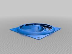
Next, install the fans. You need to check which way the fan is rotating (they only rotate one way), and install it so that the air is pulled up. Each fan should be covered with the shroud base and secured to the roof by four longer m3 bolts (up to m3x50, but m3x35 might be enough, depends on the thickness of your fan).
Then you meed to connect all the fans to the 12v power supply.
Next you need to assemble the driver for the stepper, please remember to use gradual acceleration if it's supported by the technique you use. Please pay attention that the rotation direction should be such that the spoon-like pattern on the plates “scoops” the water. The idea is that once water level goes down, we should still maximise the amount of water on the disks, the water is supposed to flow from the edges towards the center when the disks rotate. The correct rotation of the disks looks like as if the spoon pattern “scoops” the water when it rotates.
And then you just add a little bit of a solid grease (the 3d printer variety will do) onto the gears. Remove te excess grease, there shouldn't be an visible chunks remaining.
Well, that's it! By now you already tested it, so… Just put the assembly into the container, Pour tap water into the container up to approx. 1 cm below the bearing level. Mark the water level with a marker or an electrician's tape so that you can see the maximum water level easily.
This model is in public domain, can be used freely. The remixing is welcome (fusion model is included), but attribution is required. Feel free to use for commercial purposes, please keep the attribution.
| Air_Washer_V3_v36.f3d | 5.3MB | |
| Air_Washer_V3_v36.stl | 55.9MB | |
| Connector_pad.stl | 1.1MB | |
| Disk_rod.stl | 61.6KB | |
| End_connector.stl | 68.1KB | |
| Evaporating_disk.stl | 495.8KB | |
| Gears_frame_28BYJ-48.stl | 233.3KB | |
| Gears_frame_NEMA17.stl | 269.3KB | |
| Larger_gear.stl | 292.3KB | |
| Larger_gear_stem.stl | 75.5KB | |
| Leg.stl | 138.9KB | |
| Leg_bottom.stl | 266.3KB | |
| Leg_bottom_peg.stl | 74.4KB | |
| Leg_connector.stl | 750.5KB | |
| Leg_connector_bolt.stl | 1.6MB | |
| Roof.stl | 112.2KB | |
| Shroud.stl | 1.1MB | |
| Shroud_holder.stl | 148.3KB | |
| Smaller_gear.stl | 593.0KB | |
| Smaller_gear_28BYJ-48.stl | 583.6KB | |
| Smaller_gear_NEMA17.stl | 593.0KB |